
Results 1 to 29 of 29
Thread: Flooded Ammonia Part Two
-
09-03-2006, 01:58 AM #1

 Moderator
Site Moderator : and general nice guy
Moderator
Site Moderator : and general nice guy


- Join Date
- Jan 2006
- Location
- Croatia
- Age
- 68
- Posts
- 2,261
- Rep Power
- 31
Flooded Ammonia Part Two
I'm qute familiar with Howden, Mycom and Dunham-Bush. Sullair I do not know at all. Proper maintenance and normal working conditions can keep them alive for a long timeThe screw compressors are: Howden, Sullair, Mycom, and Dunham-Bush. Most of these are at least 20 years old, and all run very well.
This one what we have here is working with condensing pressure. High pressure liquid cooler and pumper drum are in paralel connection do deliver a cold liquid to coolers. First we have liquid from pumper drum until is empty. Simultaneously we close the high pressure gas line to pumper drum and open equalizing gas line from pumper drum to surge drum to start gravity liquid filling into pumper drum. In the same time SV at cold liquid line from economiser is open to deliver cold liquid until pumper drum is full again and ready to deliver liquid. This is some kind of sequential work with about 3-5 minutes sequences for almost 30 years until now.The one thing I do not like about the pumper drums is that you have to maintain a minimum gas pressure for pumping the liquid. Otherwise they are very simple to understand. You are exactly right about the NRV's.
For that reason I started this oneThis thread is getting very long. Perhaps we should start a new one??
Yes, almost forget nothing about controls and valves: old one Phillips Refrigeration, Johnson Controls, Danfoss or other..
-
09-03-2006, 07:39 PM #2
 VIP Poster
- Join Date
- Aug 2005
- Location
- USA
- Posts
- 5,302
- Rep Power
- 25
Re: Flooded Ammonia Part Two
Sullair started off by manufacturing twin screw compressors for compressed air systems. Sometime in the 1960's or 70's they started to package compressors for refrigeration applications; ammonia, *****, and helium among others.
I installed several of these and really like them. Very simple, easy to work on...
Sometime in the late 1980's they were involved in a very large heat pump system for an office building. R-22 liquid overfeed, ice banks for thermal storage, evaporative condensers, etc. An industrial refrigeration system being used for office air conditioning.
Someone miscalculated the building envelope loads and the whole thing became a legal mess. Everyone had to pay some money. Shortly after that Sullair did not sell compressors for refrigeration service anymore.
I don't know what the whole story was, but the legal problems left a bad feeling for everyone involved in the project from what I heard.
The good thing about pumper drums is that you can change the transfer rate. A little more or a little less. It is hard to do that with a mechanically pumped system.
I really prefer the mechanically pumped systems though. If you have the liquid feed valves setup properly, you can really reduce the discharge pressure on the compressors.
If you reduce the discharge pressure on the pumper drums too much, the transfer rates begin to slow down so you could run out of liquid to the evaporators.
If we can find enough to discuss, can we make it to "Flooded Ammonia, Part III?")
-
09-03-2006, 08:07 PM #3
VIP Poster
- Join Date
- Aug 2005
- Location
- USA
- Posts
- 5,302
- Rep Power
- 25
Re: Flooded Ammonia Part Two
Josip,
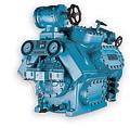
Here is a picture of a Sullair screw compressor package.
From one of my old catalogs...
They were painted about the same color of green we have on the RE forum pages.
-
09-03-2006, 10:15 PM #4
Moderator
Site Moderator : and general nice guy
- Join Date
- Jan 2006
- Location
- Croatia
- Age
- 68
- Posts
- 2,261
- Rep Power
- 31
Re: Flooded Ammonia Part Two
Somebody did some mistake. The only way out was maybe to quit with refrigeration. Today they are famous for air service. Originally Posted by US Iceman
Changing condensing pressure change the transfer rate too or you think on some other way.The good thing about pumper drums is that you can change the transfer rate. A little more or a little less.
It is hard to do that with a mechanically pumped system.
I really prefer the mechanically pumped systems though. If you have the liquid feed valves setup properly, you can really reduce the discharge pressure on the compressors.
If you reduce the discharge pressure on the pumper drums too much, the transfer rates begin to slow down so you could run out of liquid to the evaporators.
Using pumps is ok and very simple, having problem with pressure when you have a small cooling demand 2-3 roms out of 10-12.
For that reason they install double ammonia charging lines to evaporators, one from pumper drum and another one from economiser coil. This coil is smaller becuse it is working during recharging of pumper drum.
Like Star Wars or The Lord of the RingsIf we can find enough to discuss, can we make it to "Flooded Ammonia, Part III?
-
09-03-2006, 10:31 PM #5
Moderator
Site Moderator : and general nice guy
- Join Date
- Jan 2006
- Location
- Croatia
- Age
- 68
- Posts
- 2,261
- Rep Power
- 31
Re: Flooded Ammonia Part Two
Very simple and very low almost at floor level. All of them in the begining were down. Originally Posted by US Iceman
Today all of them are very high maybe for easier maintenance  . You must have scaffolds around to do service.
-
10-03-2006, 03:51 AM #6
VIP Poster
- Join Date
- Aug 2005
- Location
- USA
- Posts
- 5,302
- Rep Power
- 25
Re: Flooded Ammonia Part Two
If your systems use the 3-way valve I think we can use a larger valve port. The larger valve port will allow more gas volume at the lower pressure differential. Originally Posted by Josip
This is what I have seen.
On one system we ran the discharge pressure down very low in the winter to see what would happen. Everything worked OK except for the pumper drums (these were for transfer, not liquid overfeed). The accumulator started to fill up because the transfer rate was not fast enough. The system shut down on high liquid level.
I would expect a similar thing to happen on the liquid make-up valves (intercoolers, etc.). The lower pressure differential changes the valve capacity, so once again we need larger valve ports.
The trick is to find a way to use multiple valves, or a valve that have sufficient capacity at both conditions (minimum and design differential).
What sort of problems do you have when only 2-3 rooms are cooling? Is it the pump discharge pressure or pump suction pressure?Using pumps is OK and very simple, having problem with pressure when you have a small cooling demand 2-3 rooms out of 10-12.
This sounds like you have only one pumper drum to feed the system. Most the systems I have seen will use two pumper drums. One fills, while the other is transferring liquid to the evaporators. After one has emptied, the other drum is ready to go. They cycle back and forth to maintain liquid supply.For that reason they install double ammonia charging lines to evaporators, one from pumper drum and another one from economiser coil. This coil is smaller because it is working during recharging of pumper drum.
Can you provide a quick piping sketch of the system you describe please?
A long time ago, in a place far, far away.... Someone started to use ammonia systems!Like Star Wars or The Lord of the Rings/
-
10-03-2006, 03:58 AM #7
VIP Poster
- Join Date
- Aug 2005
- Location
- USA
- Posts
- 5,302
- Rep Power
- 25
Re: Flooded Ammonia Part Two
I think the reason everyone started to mount the compressor and motor on the oil separators is that this saved a lot of cost. No structural steel and less welding. Originally Posted by Josip
Some of the very large screws are still mounted down low. The separator shells cannot accommodate the very high weights and motor torque.
Personally I like the lower models because they are much easier to work on. You do not have to be a monkey to work on anything.
-
10-03-2006, 11:21 AM #8
Moderator
Site Moderator : and general nice guy
- Join Date
- Jan 2006
- Location
- Croatia
- Age
- 68
- Posts
- 2,261
- Rep Power
- 31
Re: Flooded Ammonia Part Two
Please can you send some piping scheme with 3-wy valves, picture can say more than thousand wordsIf your systems use the 3-way valve I think we can use a larger valve port. The larger valve port will allow more gas volume at the lower pressure differential.
This is what I have seen. Please, send some very typical and simple piping diagram
This design is not comon here and I want to learn something more...
What about HG defrost if any, when you have very low condensing pressure? Can you, please, briefly explain idea to use pumper drums for liguid transfer to receiver. Is seems to me very complicated with so many level controls, valves... We do not use that system here and maybe I cann't see benefits..On one system we ran the discharge pressure down very low in the winter to see what would happen. Everything worked OK except for the pumper drums (these were for transfer, not liquid overfeed). The accumulator started to fill up because the transfer rate was not fast enough. The system shut down on high liquid level. I did see Phillips solutions (compressor protection) but still....
It is not too big problem, only higher discharge pressure. Another, sometimes bigger, problem is due to complete design and compressor capacity. For example for 10 cold rooms you choose proper compressor. Coming down to 2-3 rooms and running compressor even at minimum capacity you can come under set point causing pump stop due to low pressure difference (RT262). Pumps cycling and that is very bad, especially for hermetic pumps. Here I mean about industrial plants where client ask to install minimum units, but you know that storyWhat sort of problems do you have when only 2-3 rooms are cooling? Is it the pump discharge pressure or pump suction pressure?
This was designed by Stal Sweden to utilize eco port on compressor and for that reason we use one pumper drum and economiser. Yes I would like to send you piping sketc but unfortunately I have only one very bad blue print copy, from time when we use ozalid paper to copy drawingsThis sounds like you have only one pumper drum to feed the system. Most the systems I have seen will use two pumper drums. One fills, while the other is transferring liquid to the evaporators. After one has emptied, the other drum is ready to go. They cycle back and forth to maintain liquid supply.
Can you provide a quick piping sketch of the system you describe please?.
Maybe I can make couple of scans and put them together to make it complete.
-
10-03-2006, 02:28 PM #9
VIP Poster
- Join Date
- Aug 2005
- Location
- USA
- Posts
- 5,302
- Rep Power
- 25
Re: Flooded Ammonia Part Two
Let me see what I can find today. I will post something if I can get the file size small enough. Originally Posted by Josip
Over here we normally use pressure regulators (we call them defrost relief valves) to control the outlet coil pressure above a saturation temperature of 0C. Most of the time these valves are set for an equivalent saturation temperature of 10C.What about HG defrost if any, when you have very low condensing pressure?
Since the defrosting pressure is set for the equivalent temperature of 10C, this establishes the minimum hot gas pressure you need. Now you have to add the pipe pressure losses to the defrost pressure setting of the valve.
This total pressure is then the minimum pressure you need for the discharge pressure.
I have worked on some systems where we were able to run the condensing temperature down to about 15C and still defrost the coils in under 30 minutes.
There are many different types of these systems. When the transfer drums push the liquid to the high-pressure receiver, the transfer drums are normally located above the receiver. A little pressure difference and gravity allow the liquid to flow into the receiver.Can you, please, briefly explain idea to use pumper drums for liquid transfer to receiver. Is seems to me very complicated with so many level controls, valves...
If the transfer drum pushes the liquid into a receiver controlled at a pressure lower than discharge pressure, you need sufficient differential to move the liquid.
In other cases, a positive displacement pump is used to transfer the liquid. The Phillips compressor protection method is one way.
As you say these are very complicated with all of the valves, small piping, controls, etc. I do not like these systems for those reasons. I prefer to keep things simple.
This sounds like pump cavitation due to decreasing compressor suction pressure from the large compressor size. The cooling loads are less than the compressor capacity, so when the suction pressure continues to decrease the pumps go into cavitation.Coming down to 2-3 rooms and running compressor even at minimum capacity you can come under set point causing pump stop due to low pressure difference...
In this case you need more capacity reduction in the system, but then you have already explained the problem.
Since you have the Adobe software, can you draw a simple sketch of the piping on paper and then scan it into a PDF?industrial plants where client ask to install minimum units...Last edited by US Iceman; 10-03-2006 at 02:30 PM. Reason: correcting quote
-
10-03-2006, 06:06 PM #10
VIP Poster
- Join Date
- Aug 2005
- Location
- USA
- Posts
- 5,302
- Rep Power
- 25
Re: Flooded Ammonia Part Two
I did find one diagram for a single pumper drum system. The dual drum system is similar as far as I can remember. Originally Posted by Josip
I hope this explains how the system is being used.
Best Regards,
US Iceman
-
10-03-2006, 07:56 PM #11
 regular poster
- Join Date
- Jan 2002
- Location
- Long Beach Ca
- Age
- 48
- Posts
- 47
- Rep Power
- 0
Re: Flooded Ammonia Part Two
hello everyone, put this link once before ,http://www.wea-site.com/papers.html makes for some good reading, well simplified. US Iceman ever work with any of the los angeles industrial people? my past company had a long relationship with mr Kohlenberger, just curious, best regards
-
10-03-2006, 08:14 PM #12
Moderator
Site Moderator : and general nice guy
- Join Date
- Jan 2006
- Location
- Croatia
- Age
- 68
- Posts
- 2,261
- Rep Power
- 31
Re: Flooded Ammonia Part Two
Hello, US Iceman
See attachments: freeeee
acad zip and pdf, you can choose
First start manually it was not nice. Not having a readable blue print drawing decide to make one in autocad. take some time but .....
Some valves and lines missing but have no nervs to finish, hope it will be ok if not....ask
Stan1488 your link seems pretty good, need some time to read it, thanks
-
10-03-2006, 08:17 PM #13
 improving poster
- Join Date
- Mar 2006
- Location
- Frederikssund
- Age
- 49
- Posts
- 24
- Rep Power
- 0
Re: Flooded Ammonia Part Two
Hello
just entered RE i just love ammonia iam form-Denmark home of Gram Danfoss and Sabroe, i have workede for Sabroe and Yorkref, i can see that you are a fan of sabroe Stan1488,
-
10-03-2006, 08:22 PM #14
Moderator
Site Moderator : and general nice guy
- Join Date
- Jan 2006
- Location
- Croatia
- Age
- 68
- Posts
- 2,261
- Rep Power
- 31
Re: Flooded Ammonia Part Two
Welcome Casper,
nice to have some more guys loving that stinking but natural fluid
-
10-03-2006, 08:30 PM #15
improving poster
- Join Date
- Mar 2006
- Location
- Frederikssund
- Age
- 49
- Posts
- 24
- Rep Power
- 0
Re: Flooded Ammonia Part Two
hey josip
I just lookede at the system
what is?
The temp of the eco?
the temp of the rooms?
the pressof the eco?
-
10-03-2006, 08:48 PM #16
VIP Poster
- Join Date
- Aug 2005
- Location
- USA
- Posts
- 5,302
- Rep Power
- 25
Re: Flooded Ammonia Part Two
Hi guys,
Welcome to the RE forum kasperDK. It is very nice to have other ammonia people to talk to.
I'll try to answer some of the questions...
I know some people in sunny southern California. The name you mentioned sounds very familiar. When I used to work for a manufacturer I spent quite a lot of time with an ex-Frigid Coil person working on some air unit designs. I know the guys over at RETA National Headquarters in Salinas. Originally Posted by stan1488
Thank you for re-posting the web site link. I will review that also.
The drawing looks fine. I need to spend some time reviewing it. Originally Posted by Josip
I agree. The more people the better the discussion is. Originally Posted by Josip
-
10-03-2006, 09:03 PM #17
VIP Poster
- Join Date
- Aug 2005
- Location
- USA
- Posts
- 5,302
- Rep Power
- 25
Re: Flooded Ammonia Part Two
Hi Josip,
Looked at your drawing.
It looks like the high pressure gas for pumping liquid comes from the receiver. When the pumper drum is filling, the liquid from the economizer is flowing to the evaporators.
After the pumper drum is full, the high pressure gas from the receiver pushes the liquid out of the drum and into the liquid line.
One thing I have a question about is the liquid from the economiser. It is at discharge pressure. When the pumper drum transfers liquid into the liquid line is there a NRV in the liquid line from the economiser (before the liquid line from the pumper drum)?
If the gas pressure to the pumper drum is lower than the liquid line pressure from the economiser, the liquid would not flow out of the pumper drum. Unless there is some elevation difference for gravity.
Or, are there other control valves which help this?
Perhaps I am missing something???
-
10-03-2006, 09:15 PM #18
improving poster
- Join Date
- Mar 2006
- Location
- Frederikssund
- Age
- 49
- Posts
- 24
- Rep Power
- 0
Re: Flooded Ammonia Part Two
i have the same idea but i think ther are a ON/OFF valve in the liquid line form the economiser ther are controled for the Pumper drum level indikator
How dos this system react wenn you use HG defrost?
-
10-03-2006, 09:19 PM #19
improving poster
- Join Date
- Mar 2006
- Location
- Frederikssund
- Age
- 49
- Posts
- 24
- Rep Power
- 0
Re: Flooded Ammonia Part Two
Ther are a ON/off valve underthe suction return line to the seperator this must be controled form the level indikator in the Pumper drum
-
10-03-2006, 09:22 PM #20
VIP Poster
- Join Date
- Aug 2005
- Location
- USA
- Posts
- 5,302
- Rep Power
- 25
Re: Flooded Ammonia Part Two
That makes a lot of sense. When the pumper drum is ready to discharge liquid, the liquid line solenoid valve would close. Originally Posted by kasperDK
The pressure in the liquid line would decrease due to the lower evaporating pressure. When the liquid line pressure is low enough, the liquid would then flow from the pumper drum.
That is a good question. I would like to hear from Josip about this.How dos this system react when you use HG defrost?
-
10-03-2006, 09:27 PM #21
VIP Poster
- Join Date
- Aug 2005
- Location
- USA
- Posts
- 5,302
- Rep Power
- 25
Re: Flooded Ammonia Part Two
Now I see the valve. That completes the picture and answers the question.
-
10-03-2006, 11:13 PM #22
Moderator
Site Moderator : and general nice guy
- Join Date
- Jan 2006
- Location
- Croatia
- Age
- 68
- Posts
- 2,261
- Rep Power
- 31
Re: Flooded Ammonia Part Two
Sorry guys,
forget to put the marks on solenoids and NRV's
On the liqid line before pumper drum is a flap type NRV (reason is; liquid by gravity force can open it to fill up pumper drum) after PD is normal check valve because we are using HP gas to push the liquid by opening left valve group on the top of PD. When we get the signal that PD is empty valve groups on the top of PD cycle (left OFF/right ON) to close the HP gas to equalize pressures in PD and surge drum and start gravity filling.
Simultaneously with right valve group over PD we have ON signal to solenoid valve on liqiud line from economiser to evaporators. This liquid is some kind of make up (notice there is not other line for that) for complete system and liquid delivery during refilling of PD.
There is not any HG defrost becuse this liquid enters machine for butter homogenisation. It is continuous process to produce butter and evaporating temp is -15C but for safety reasons (reduced production or something else) there is HG injection point to prevent freezing of butter and stuck of machinery. Each evaporator is eguipped with pressure and temperature controled valves becuse the quality of butter depends on process temperature.
Complete valve stations for each evaporator (lot of different kind are installed there) were Danfoss. Process plant piping diagram I do not have but when I was there before 20+ years I was impressed and I asked about everything. Later on I was there couple of times for some services and use that time to study complete plant.Last edited by Josip; 11-03-2006 at 09:25 AM. Reason: correction of miswrite
-
11-03-2006, 03:25 AM #23
VIP Poster
- Join Date
- Aug 2005
- Location
- USA
- Posts
- 5,302
- Rep Power
- 25
Re: Flooded Ammonia Part Two
Josip,
A very interesting system. Thank you for showing it to us.
Best Regards,
US IcemanLast edited by US Iceman; 11-03-2006 at 03:25 AM. Reason: spelling
-
11-03-2006, 11:29 PM #24
 regular poster
- Join Date
- Dec 2005
- Location
- Norfolk, England
- Age
- 66
- Posts
- 132
- Rep Power
- 19
Re: Flooded Ammonia Part Two
Hi. Ammonia Just love it, The best refrigeration liquid and gas you can use.
-
12-03-2006, 08:45 PM #25
 VIP Poster
- Join Date
- Jun 2001
- Location
- N.Ireland
- Age
- 51
- Posts
- 1,630
- Rep Power
- 25
Re: Flooded Ammonia Part Two
Hi Guys
I recently designed a system for pumping all the ammonia charge out of a brine chiller on a cheese plant, prior to the tube side being cleaned by a CIP (Clean in place) system. I based my system on the Sabroe "Thermo Pump" used to cool oil in recip compressors.
I thought I have designed something unique
The process was as follows. using motorised valves.
Shut off the liquid and pump out.
Shut the suction off, evaporat pressure reg in circuit
Open a drain valve at the bottom of the chiller to a drain vessel
Pressure with hot gas, whilst opening a vent to the outlet side of the suction press reg
Close drain valve on a low level cut out and stop the hot gas and start the CIP
After CIP the chiller can be ran as normal with the hot gas used to push the liquid from the drain vessel to the main liquid line.
It seems I have seen a drawing somewhere for a pumper system and copyied it without thinking
Still I think pumper systems are a good idea
Kind Regards. Andy.
-
12-03-2006, 11:15 PM #26
VIP Poster
- Join Date
- Aug 2005
- Location
- USA
- Posts
- 5,302
- Rep Power
- 25
Re: Flooded Ammonia Part Two
I think the system Andy described is similar to some ice cream machines I have heard about. I can't remember the name, but I believe they German. Apologies to the company if I'm wrong.
-
29-01-2009, 10:17 PM #27
 Registered User
Hey, I am new to : RE
Registered User
Hey, I am new to : RE
- Join Date
- Jan 2009
- Location
- Indiana
- Posts
- 8
- Rep Power
- 0
Re: Flooded Ammonia Part Two
All I work on is Sullair Refrigeration products, if you have questions contact me at Mid-States Refrigeration.
-
30-01-2009, 01:09 AM #28
VIP Poster
- Join Date
- Aug 2005
- Location
- USA
- Posts
- 5,302
- Rep Power
- 25
Re: Flooded Ammonia Part Two
How are Jack and Tim doing? I have not talked to them for some time... Originally Posted by Sullair Refrig
 If all else fails, ask for help.
-
05-02-2009, 03:45 PM #29
 VIP Poster
- Join Date
- Jan 2006
- Location
- Valrico, Florida
- Posts
- 509
- Rep Power
- 19
Re: Flooded Ammonia Part Two
We get all our parts for the Sullairs through Mid-States. Welcome to RE Originally Posted by Sullair Refrig

Similar Threads
-
Want to be trained as an ammonia operator
By Randy Williams in forum NH3Replies: 7Last Post: 26-11-2008, 08:15 PM -
part p
By eggs in forum ElectricalReplies: 25Last Post: 15-11-2007, 08:55 PM -
New Ammonia Certification in United States
By JerrydNH3 in forum NH3Replies: 11Last Post: 15-08-2006, 03:10 PM -
HFCs for flooded systems?
By garyb in forum RefrigerantsReplies: 15Last Post: 21-04-2006, 10:02 PM -
Flooded Ammonia Refrigeration
By stcornish in forum NH3Replies: 65Last Post: 17-03-2006, 03:33 AM
