
Results 1 to 10 of 10
Thread: Wiring diagram for ylaa 0195
-
26-01-2021, 06:13 AM #1

 Registered User

- Join Date
- Oct 2008
- Location
- FRANCE
- Age
- 58
- Posts
- 13
- Rep Power
- 0
Wiring diagram for ylaa 0195
Good morning all !
I am looking for an electrical diagram for a YLAA 0195 groupYLAA 0195.jpgYLAA 0195.jpg
(Photo Namme plate) Thank you for your help!
Take care of yourself !
Patrick
-
26-01-2021, 01:30 PM #2
 Super Moderator

- Join Date
- Oct 2001
- Location
- Nottingham UK
- Posts
- 5,668
- Rep Power
- 51
Re: Wiring diagram for ylaa 0195
Closest Model I could find https://docs.johnsoncontrols.com/chi...eat-Exchangers
-
26-01-2021, 04:49 PM #3
Registered User
- Join Date
- Oct 2008
- Location
- FRANCE
- Age
- 58
- Posts
- 13
- Rep Power
- 0
Re: Wiring diagram for ylaa 0195
Thanks for your help Frank !
-
27-01-2021, 06:18 PM #4
 Super Moderator
- Join Date
- Sep 2007
- Location
- Somerset
- Age
- 69
- Posts
- 4,697
- Rep Power
- 46
Re: Wiring diagram for ylaa 0195
Hi Patrick.
Check your email.
Hopefully the files are not too large for you to receive them.
What exactly is your issue?
Good Luck
GrizzlyDespite the High Cost of Living it still remains Popular!
-
28-01-2021, 07:35 AM #5
Registered User
- Join Date
- Oct 2008
- Location
- FRANCE
- Age
- 58
- Posts
- 13
- Rep Power
- 0
Re: Wiring diagram for ylaa 0195
Hi Grizzly
Thanks for your help !
My problem is, before me, the another company to modify the wiring
on the fan contactors, and the fan turn constantly , compressors on and off situation ! !! (May be in summer, in temporary situation, but no in Winter!!)
They did not see that the pressure HP fan sensor, was defective on the first fan !!
I have to change the pressure sensor and i want to place the wirring in original conformity,
and no wirring diagram in place!
Thanks
Patrick
-
28-01-2021, 04:31 PM #6
Super Moderator
- Join Date
- Sep 2007
- Location
- Somerset
- Age
- 69
- Posts
- 4,697
- Rep Power
- 46
Re: Wiring diagram for ylaa 0195
Does this chiller not have the wiring diagrams on the inside of the Door to the Main panel.
There are wiring diags in the manual info you have.
Good luck.Despite the High Cost of Living it still remains Popular!
-
28-01-2021, 06:39 PM #7
Registered User
- Join Date
- Oct 2008
- Location
- FRANCE
- Age
- 58
- Posts
- 13
- Rep Power
- 0
Re: Wiring diagram for ylaa 0195
Merci Grizzly pour toutes les informations!
Aucun câblage à l'intérieur du panneau électrique! (Machine fabriquée par Spain Factory, Sabadell Barcelona)
J'ai essayé sur weeb, sans succès!
Ce manuel que vous m'envoyez, est exactement pour ma machine, avec ceci,
un bidon pour résoudre la situation, merci
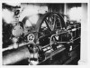
Question: mon refroidisseur est équipé de ceci (Photo): Quelle est la fonction?
Réfrigérant de stockage, sous-refroidisseur, situation de basse température extérieure ???
C'est optionnel? YLAAA 0195 -Cond .jpgYLAAA 0195 -Cond .jpgYLAAA 0195 -Cond .jpg
Le tube supérieur Tue est connecté au Hp,
Le tube inférieur gauche est connecté uniquement à l'échangeur à plaques d'entrée avec une vanne sélénoïde,
Le tube inférieur droit est connecté à la batterie inférieure du condenseur,
Si vous avez les informations pour cela?
Merci Grizzly !!
-
28-01-2021, 07:16 PM #8
Super Moderator
- Join Date
- Sep 2007
- Location
- Somerset
- Age
- 69
- Posts
- 4,697
- Rep Power
- 46
Re: Wiring diagram for ylaa 0195
Patrick
I had to translate the page into english.
If I remember correctly, I could be wrong?
Someone feel free to correct me if I am!
But i think that is a Oil Cooling circuit using a small part of the condenser?
Check in the manual or just follow the pipes!
GrizzlyDespite the High Cost of Living it still remains Popular!
-
29-01-2021, 01:21 PM #9
Super Moderator
- Join Date
- Sep 2007
- Location
- Somerset
- Age
- 69
- Posts
- 4,697
- Rep Power
- 46
Re: Wiring diagram for ylaa 0195
Hi Patric
I have been looking at this again, it may be part of a circuit used for low ambient running.
As I said before tracing it out may clarify the useage?
The more i look at it the more i think its for low ambient operation conditions.
Good luck GrizzlyDespite the High Cost of Living it still remains Popular!
-
01-02-2021, 07:00 AM #10
Registered User
- Join Date
- Oct 2008
- Location
- FRANCE
- Age
- 58
- Posts
- 13
- Rep Power
- 0
Re: Wiring diagram for ylaa 0195
Hi Grizzly
I'm Sorry for the Translation on the last message !!
You are right, that's it !!
the system makes it possible to inject directly into the evaporator inlet
via à sélénoid valve, when the externals conditions are low.
I also noticed that York Factory, placed à small heating resistor, ont the TXV Head,
i suppose it's for to help TXV opening in cold weather.
Thank you for your help Grizzly !!
Patrick

