
Results 151 to 200 of 224
Thread: Strange TXV setup
-
15-03-2010, 07:01 AM #151

 VIP Poster


- Join Date
- Apr 2001
- Location
- New Port Richey, Florida - USA
- Age
- 79
- Posts
- 5,071
- Rep Power
- 35
Re: Strange TXV setup
If the orifice is oversized and the bulb charge has not migrated, then the valve should be hunting. Originally Posted by mad fridgie

-
15-03-2010, 09:29 AM #152
 VIP Poster
- Join Date
- Aug 2009
- Location
- New Zealand
- Age
- 60
- Posts
- 2,554
- Rep Power
- 26
Re: Strange TXV setup
It can only hunt if there is enough refrigerant, and if the minimum close position of the TEV produces less cooling effect than the load. Originally Posted by Gary
Chef has mastered critical charge, thus acting like a fixed orifice. (all 4 plates cgarged)
So the question should be how do you prove if the charge within the TEV has migrated.
-
15-03-2010, 04:23 PM #153
VIP Poster
- Join Date
- Apr 2001
- Location
- New Port Richey, Florida - USA
- Age
- 79
- Posts
- 5,071
- Rep Power
- 35
Re: Strange TXV setup
The problem at this point is we can't run the system, make adjustments and take measurements. Originally Posted by mad fridgie
The TXV is no doubt cranked wide open. It needs to be adjusted to a central setting for a starting point. We need to know the receiver outlet subcooling, evap outlet superheat and compressor inlet superheat near beginning of cycle and near end of cycle.
At this point all we can do is make assumptions and jump to conclusions.
Chef, is the bulb insulated?
Does the system have a sightglass?Last edited by Gary; 15-03-2010 at 04:40 PM.
-
15-03-2010, 05:10 PM #154
VIP Poster
- Join Date
- Apr 2001
- Location
- New Port Richey, Florida - USA
- Age
- 79
- Posts
- 5,071
- Rep Power
- 35
Re: Strange TXV setup
Frost after the HX would indicate that there is sufficient refrigerant for the conditions. If the bulb is insulated, the coil outlet suction line temp should be low enough for the charge to migrate back to the bulb... and at some point during the cycle the load exceeds the minimum close position flow, in which case it should modulate (and hunt if the orifice is too large)... therefore the TXV is adjusted wide open and/or the bulb is not insulated. Originally Posted by mad fridgie
-
16-03-2010, 06:06 AM #155
 Veteran Poster
- Join Date
- Jun 2007
- Location
- At sea
- Posts
- 367
- Rep Power
- 17
Re: Strange TXV setup
Gary - the last two plates freeze to their design spec and the system is turned off manually when it is ready, if you add a little gas it starts to freeze back to compressor, its not a controlled system its run by feel the and stop the timer thats why it has never got back to the compressor (yet).
The bulb is not insulated but taped on with metal film (think cling film made of metal) and system has a sightglass which is pure liquid at all times. A quick guess at the SC is 2 to 4 dergrees but I am away at the moment and dont have the data to hand.
There are many points I have read and would like to discuss but for a few days the big cyclone is taking up many peoples attention.
I still think its running from a nearly fixed temp in the freezer acting on the diaphragm and the pressure changes are just small changes to orifice size - not control but just change.
Chef
-
16-03-2010, 06:45 AM #156
VIP Poster
- Join Date
- Apr 2001
- Location
- New Port Richey, Florida - USA
- Age
- 79
- Posts
- 5,071
- Rep Power
- 35
Re: Strange TXV setup
The bulb must be tightly strapped and heavily insulated. Originally Posted by Chef
Is the sightglass at the receiver outlet?
-
16-03-2010, 09:39 PM #157
VIP Poster
- Join Date
- Apr 2001
- Location
- New Port Richey, Florida - USA
- Age
- 79
- Posts
- 5,071
- Rep Power
- 35
Re: Strange TXV setup
Most compressor manufacturers call for a minimum of 8-11K SH at the compressor inlet. At 2psi, the saturation temp is about -27C. If we add 8-11K SH, that gives us a minimum suction line temp of 16-19C at the compressor inlet. At those temps we would expect frost all the way back to, and maybe even on the compressor. Originally Posted by Chef
In truth, the suction line temp could be even lower, down to about 5C, without causing any damage. Frost at the compressor inlet does not necessarily indicate flooding.
-
16-03-2010, 11:54 PM #158
Veteran Poster
- Join Date
- Jun 2007
- Location
- At sea
- Posts
- 367
- Rep Power
- 17
Re: Strange TXV setup
Its tight strapped but no insulation, even so that pipe never gets closer than say 6C to being as cold as the valve so it does not seem relevant at the moment. Originally Posted by Gary
Sight glass is after the filter drier, about 2 feet from receiver.
Chef
-
17-03-2010, 03:52 AM #159
VIP Poster
- Join Date
- Apr 2001
- Location
- New Port Richey, Florida - USA
- Age
- 79
- Posts
- 5,071
- Rep Power
- 35
Re: Strange TXV setup
Hmmm... The sightglass shows solid liquid and the orifice is adequate, if not oversized. This should be easily capable of flooding the plates. Originally Posted by Chef
Yet the suction line at the final evap outlet does not get colder than the freezer air, which is 17K above SST.
This might lead us to believe there is a restriction between the sightglass and the orifice (undersized/kinked liquid line, restricted HX, partially plugged inlet screen, etc.).
On the other hand, just a little more refrigerant can frost the suction line after the HX.
There is something very wrong with this picture.Last edited by Gary; 17-03-2010 at 04:24 AM.
-
17-03-2010, 04:15 AM #160
 VIP Poster
- Join Date
- Mar 2009
- Location
- KZN, South Africa
- Age
- 64
- Posts
- 2,212
- Rep Power
- 20
Re: Strange TXV setup
In your part of the world, insulating the bulb should be mandatory practice. The slightest disturbance on the sensing bulb eg. from a breeze, or cooling fan, can make the whole system incredibly sensitive. If it is an MOP bulb, then all the worse. Originally Posted by Chef
I saw this first-hand last week. Took a fair process of elimination to locate the main disturbance driver.
Water drips on the bulb can also be interesting disturbance drivers. Engineering Specialist - Cuprobraze, Nocolok, CD Technology
Rarefied Technologies ( SE Asia )
-
17-03-2010, 01:16 PM #161
 rookie poster
- Join Date
- Dec 2001
- Location
- Ft Lauderdale FL.
- Posts
- 16
- Rep Power
- 0
Re: Strange TXV setup
I tried to look back over the last the 155 posts to find answers to the following questions:
Why is the installation of heat exchanger being question?
What is causing the excessive high pressure on this system?
Who fabricated the holding plates?
What temperature are plate solutions set to freeze at? Plates Set to freeze at less than zero are difficult to freeze with 134a refrigerant.
What is the heat load of freezer box?
How much refrigerant is in this system?
When plates are frozen how long will plates stay frozen?
Refrigerant phase change at end of evaporator plates has happened, is there a chance test nitrogen may still be in system contaminating refrigerant.
How was it determined that there are no major restrictions to flow after TXV in low pressure side of system?
Chef, Someone suggested earlier to move sense bulb to line after freezer plates this may move refrigerant phase change back to freezer If not there could be a major blockage somewhere prior to refrigerator plates.
Having spent twenty years manufacturing more than hundred holding plates and selling engine drive boat refrigeration kits to amateur do it yourselfers I use a simple approach in trouble shoot plate system performance.
When servicing a new system add only one pound of refrigerant and start compressor then if suction pressure after start is less than 10 psi add refrigerant to achieve at least 10 psi. Because refrigerant sight glasses are not all the same I recommend that additional refrigerant to eliminate bubbles be avoided until frost is visible on exit line of last plate. When the small automotive receiver is used a full charge on most small systems is 2 to 3 pounds of refrigerant adding more than this only fluids seawater condenser.
The boating industry standards for one HP engine drive refrigerant piping was set by designs from Crosby, Grunert, Frigoboat and SeaFrost. All piping from TXV through plates was ½ in OD. Suction line piping from plates to compressor are either ½ inch OD or ½ inch ID. Crosby and Grunert both used heat exchangers between liquid and suction lines. Because seawater was used as a condenser cooling medium a manually operated seawater bypass was used to control super cooling if high side pressure was too low. Most condensers were oversized to allow for cruising in tropical waters. On system designed and sold in cool climates like Seafrosts units or units from companies in the northwest refrigerant charges must be reduced or compressor needs to be operated at a lower rpm.
All of the above engine driven drive system seem to demonstrate the same pressures and temperatures as refrigerant is free to flow through normal phase changes. I was contracted to train six mechanics from three charter boat companies in the islands. In two weeks we boarded and tested around 40 boat engine drive refrigerators. Most systems were one holding plates some had two or three plates. Each units performance was measures by gauge pressures, plate freezing time and frost migration. On systems that performed well high pressure was between 135 and 120. Temperature of liquid line between filter/dryer and TXV was around 115 degree F. TXV temperature after 10 minutes running time was frosted and too cold to keep hand on. Light frost forming on line between plates on and two. Frost eventually was present on line leaving last plate. After plates were frozen compressor temperatures were cool. Suction pressure dropped to zero or 10 inches vacuum.
When you consider that the coils inside a holding plates are the same as coils in evaporator the only difference is in the heat absorption dynamics of eutectics solution is much slower than finned plate evaporators. If standard evaporators are efficient because the heat absorbing phase change occurs shortly after interring evaporator then TXV superheat must be effective in first holding plate. Years ago I had a open top holding plate on test stand and using a super heat bulb test chamber I am sure these tools are no longer available refrigerant was vented to cool bulb, I could monitor affects of superheat change on coils ice formation. If refrigerant phase change do not occur in the first plate that plate will not freeze.
-
17-03-2010, 03:39 PM #162
VIP Poster
- Join Date
- Apr 2001
- Location
- New Port Richey, Florida - USA
- Age
- 79
- Posts
- 5,071
- Rep Power
- 35
Re: Strange TXV setup
In every part of the world the bulb must always be insulated. Its purpose, its very reason for existence is to sense the suction line temperature and ONLY the suction line temperature. It cannot accurately do so if it is exposed to the surrounding air. The temperature sensed by that bulb controls the flow of refrigerant throughout the system. Originally Posted by desA
This is one of those seemingly small details that can make a HUGE difference.Last edited by Gary; 17-03-2010 at 04:11 PM.
-
21-03-2010, 03:39 AM #163
Veteran Poster
- Join Date
- Jun 2007
- Location
- At sea
- Posts
- 367
- Rep Power
- 17
Re: Strange TXV setup
Hope all this helps clear the problem for you Originally Posted by RLK
Chef
-
21-03-2010, 03:49 AM #164
Veteran Poster
- Join Date
- Jun 2007
- Location
- At sea
- Posts
- 367
- Rep Power
- 17
Re: Strange TXV setup
Exactly - its a system that works (with dumb luck as you mentioned earlier) and there are little or no signs of why it works but wrongly. Everything looks right except the SH at the compressor and that is so delicate with charge. Originally Posted by Gary
There is no blockage as system was flushed with flushing liquid several times and tested for flow with a manometer system.
DesA points out that the bulb should be insulated (agreed) but it still wont make any difference as it never gets colder than the TXV and Mad Fridgie reckons the #4 could still provide enough flow at minimum turn down - could be onto something there.
ChefLast edited by Chef; 21-03-2010 at 03:53 AM.
-
21-03-2010, 04:08 AM #165
VIP Poster
- Join Date
- Apr 2001
- Location
- New Port Richey, Florida - USA
- Age
- 79
- Posts
- 5,071
- Rep Power
- 35
Re: Strange TXV setup
Adding charge drops the SH (drops the suction line temp). So... Originally Posted by Chef
Insulate the bulb and add charge. The suction line temp will drop until the bulb temp is below the TXV temp and will thus regain its charge. If the SC is then excessive, there is a restriction.
A restriction could be an undersized or kinked liquid line, plugged TXV inlet screen, restrictive HX, etc..
-
21-03-2010, 04:26 AM #166
Veteran Poster
- Join Date
- Jun 2007
- Location
- At sea
- Posts
- 367
- Rep Power
- 17
Re: Strange TXV setup
Except if his Madness is right (usually is) the #4 is too big and works only with migration so if the bulb is allowed to regain control it might not be able to turn down enough. Originally Posted by Gary
So put in a smaller orifice and wont wont work properly till the bulb eventually gains control if it ever does.
Not sure I like that scheme of things
Chef
-
21-03-2010, 04:42 AM #167
VIP Poster
- Join Date
- Apr 2001
- Location
- New Port Richey, Florida - USA
- Age
- 79
- Posts
- 5,071
- Rep Power
- 35
Re: Strange TXV setup
Once the bulb is in control... if the TXV hunts, the orifice is oversized. Originally Posted by Chef
-
21-03-2010, 04:43 AM #168
VIP Poster
- Join Date
- Mar 2009
- Location
- KZN, South Africa
- Age
- 64
- Posts
- 2,212
- Rep Power
- 20
Re: Strange TXV setup
Adequate bulb insulation is a must. Do that & monitor the results.
Adjusting charge, or orifice, or a number of other things can come later.
Hunting can come about due to a number of reasons, not only charge, or orifice-related. Take a close look at the height between TXV actuating plate & bulb, orientation of filter-drier, liquid-line feed into TXV (important), size of external balance line. Once the pipework is correctly set up & the bulb adeqately insulated from environmental effects, this will be a good start.Last edited by desA; 21-03-2010 at 04:47 AM.
Engineering Specialist - Cuprobraze, Nocolok, CD Technology
Rarefied Technologies ( SE Asia )
-
21-03-2010, 05:00 AM #169
VIP Poster
- Join Date
- Apr 2001
- Location
- New Port Richey, Florida - USA
- Age
- 79
- Posts
- 5,071
- Rep Power
- 35
Re: Strange TXV setup
Hmmm... two more plates and a HX were added, with presumably the same liquid line. An undersized liquid line would not be out of the question.
-
21-03-2010, 09:46 AM #170
Veteran Poster
- Join Date
- Jun 2007
- Location
- At sea
- Posts
- 367
- Rep Power
- 17
Re: Strange TXV setup
Now you will have to explain this one, 3/8" line - same compressor, suction controlled flow rate - what can possibly get outside of the parameters acceptable for this line by adding plates. Originally Posted by Gary
Speculations about many things are maybe OK but it does not get us any closer to understanding how the system worked as it was.
I am still convinced it was a critically charged orifice system not under txv control and have yet to see any compelling evidence otherwise. No blockages, no kinks, no hunting, line sizes OK and orientation of filter drier OK - though that is also a scratch the head item - what has it really got to do with the issue at hand?
Chef
-
21-03-2010, 10:37 AM #171
VIP Poster
- Join Date
- Mar 2009
- Location
- KZN, South Africa
- Age
- 64
- Posts
- 2,212
- Rep Power
- 20
Re: Strange TXV setup
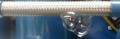
Do you have any details of the liquid line details prior to entry into the TXV? The route from condenser exit, through sightglass, flter-drier, into TXV are in mind here.
The piece of pipe immediately preceeding the txv is incredibly important in systems where txv operation is marginal, for whatever reason. This follows general basic common-sense design principles for control valves.
If you could post a picture of this set-up, I'm almost convinced we will find an explanation for part of the system behaviour.
(I had such a case-in-point a week, or so, ago. Was able to adjust the pipework in such a way that the system became rock-solid stable, off a system that was previously totally uncontrollable. It too had been acting as a fixed-orifice system until remedied).Last edited by desA; 21-03-2010 at 10:40 AM.
Engineering Specialist - Cuprobraze, Nocolok, CD Technology
Rarefied Technologies ( SE Asia )
-
21-03-2010, 02:23 PM #172
VIP Poster
- Join Date
- Apr 2001
- Location
- New Port Richey, Florida - USA
- Age
- 79
- Posts
- 5,071
- Rep Power
- 35
Re: Strange TXV setup
The TXV bulb charge is sensing freezer temp or it is sensing chiller temp. Either way it is not at its minimum flow position. It is running wide open with an orifice that is at least adequate if not oversized. Originally Posted by Chef
If there was solid liquid at the orifice the system would be flooded. Therefore, there is solid liquid at the sightglass but not at the orifice... ergo there is a restriction in between. Adding refrigerant drops the suction temp because it is overcoming the restriction.Last edited by Gary; 21-03-2010 at 02:28 PM.
-
21-03-2010, 03:58 PM #173
rookie poster
- Join Date
- Dec 2001
- Location
- Ft Lauderdale FL.
- Posts
- 16
- Rep Power
- 0
Re: Strange TXV setup
The only times I have seen these conditions before was when a major restriction after first plates increased their pressure or when freezer plates have no eutectic solution in them. If the freezer plates are SeaFrosts vertical cast aluminum plates the front cover sealant has failed before allowing solution to leak out. For a -20 C solution plate to freeze solid suction pressure on this type system needs to reach a vacuum of 9 inches. What is line temperature after each plate when compressor suction pressure is 4 psi or lower?
I would use a #1 orifice as it reduces fluid back problems although it extends first days pull down time. A #2 orifice will better match combined eutectic plates Btu capacity.
-
21-03-2010, 04:16 PM #174
VIP Poster
- Join Date
- Apr 2001
- Location
- New Port Richey, Florida - USA
- Age
- 79
- Posts
- 5,071
- Rep Power
- 35
Re: Strange TXV setup
If the restriction were after the first plates, then the first plates would not be at -20C. The restriction must therefore be before the orifice. Originally Posted by RLK
-
21-03-2010, 06:27 PM #175
rookie poster
- Join Date
- Dec 2001
- Location
- Ft Lauderdale FL.
- Posts
- 16
- Rep Power
- 0
Re: Strange TXV setup
If restriction were before TXV this restriction should cause a pressure drop and line cooling after restriction. SH
between TXV and sense bulb is very high but what is SH between each plate and sense bulb?
-
21-03-2010, 07:27 PM #176
VIP Poster
- Join Date
- Apr 2001
- Location
- New Port Richey, Florida - USA
- Age
- 79
- Posts
- 5,071
- Rep Power
- 35
Re: Strange TXV setup
I agree. Originally Posted by RLK
On my P/T chart -20C is about 4.5psi. In order to drop the plate temp to -20C, the pressure in the first plates must be somewhat less than 4.5psi. The pressure at the compressor inlet is 2psi, so the pressure drop from the first plates to the compressor can be no more than 4.5-2=2.5psi and in fact must be somewhat less than 2.5psi... probably more like 1-1.5psi. Originally Posted by RLK
Last edited by Gary; 21-03-2010 at 07:33 PM.
-
21-03-2010, 08:28 PM #177
VIP Poster
- Join Date
- Aug 2009
- Location
- New Zealand
- Age
- 60
- Posts
- 2,554
- Rep Power
- 26
Re: Strange TXV setup
Sorry gentlemen, I have been away for a week (sales show, i was like a duck out of water)
Chef has shown that this is a critical charge working on a fixed orifice, regardless if the system is right or wrong. If he added more refrigerant then his fresh products froze. This shows that "most" but not all of the refrigeration effect in the chillers was produced by sensible cooling, which leads to real increased superheat. The superheat entering the compressor is further increased due to the suction liquid HX.
What seem to be upsetting the applecart is the full sight glass, If we assume that the sightglass is an aid to charging and not a definite method, then we could ignore the sightglass, then the system as charged is acting as one would expect. Critical charged system.
Adding more refrigerant will bring the TXV into play, either correct control if orifice is the correct size or some level of hunting if oversized, either way at this point we do not have a low enough superheat to close the valve.
There are no mystery pressure drops!
What is required is some form of reduction of heat transfer between the plates and the chiller boxes (to ensure product does not freeze)
A full compliment of refrigerant then can be added. At this point can you see if the valve seletion is correct.
I would add a suction accumulator, just as a measure of protection.
Insulating the bulb always a good idea, but at this stage has no real relevence.
I am with RLK use a number 2 orifice.
The number one goal of this system is to keep the products frozen and chilled, the system works as a critical charge.
-
21-03-2010, 09:04 PM #178
VIP Poster
- Join Date
- Apr 2001
- Location
- New Port Richey, Florida - USA
- Age
- 79
- Posts
- 5,071
- Rep Power
- 35
Re: Strange TXV setup
A full sightglass with high SH proves that there is indeed a restriction. We can view the full sightglass as a guide and compensate by adding refrigerant... however this backs up liquid upstream from the sightglass and raises high side pressure, thus raising energy usage.
-
21-03-2010, 09:44 PM #179
VIP Poster
- Join Date
- Apr 2001
- Location
- New Port Richey, Florida - USA
- Age
- 79
- Posts
- 5,071
- Rep Power
- 35
Re: Strange TXV setup
Apparently I missed the post where Chef said adding refrigerant froze the products? Originally Posted by mad fridgie
-
21-03-2010, 09:48 PM #180
VIP Poster
- Join Date
- Aug 2009
- Location
- New Zealand
- Age
- 60
- Posts
- 2,554
- Rep Power
- 26
Re: Strange TXV setup
It could be as simple as a bit of flash gas forming in the liquid line (after the sight glass) this would reduce mass flow through the valve, increasing the charge would increase head pressure, a increase actual mass flow through the valve, which in turns increase the nett refrigeration effect, which in turn increases the total heat of rejection. At present the condensor is only running about a 5/6C split, therefore only a small amount of liquid sub-cooling is possible. Originally Posted by Gary
The main problem is increased refrigeration effect freezes the fresh product, hence reducing the refrigerant charge resolves the problem, (less latent energy being transfered in the chiller plates) at the expense of the compressor (very high superheat)
-
21-03-2010, 09:59 PM #181
VIP Poster
- Join Date
- Aug 2009
- Location
- New Zealand
- Age
- 60
- Posts
- 2,554
- Rep Power
- 26
Re: Strange TXV setup
Page 1 , 37 Originally Posted by Gary
Frozen lettice
-
21-03-2010, 10:02 PM #182
VIP Poster
- Join Date
- Apr 2001
- Location
- New Port Richey, Florida - USA
- Age
- 79
- Posts
- 5,071
- Rep Power
- 35
Re: Strange TXV setup
The restriction is probably a relatively minor point for this particular system, assuming the high side pressure does not rise substantially with increased charge. Originally Posted by mad fridgie
Insulating the bulb and increasing the charge should activate the bulb and put the TXV in control. The orifice should also be downsized if it causes the valve to hunt. And the plates should be shielded if the products freeze.
-
21-03-2010, 10:13 PM #183
VIP Poster
- Join Date
- Aug 2009
- Location
- New Zealand
- Age
- 60
- Posts
- 2,554
- Rep Power
- 26
Re: Strange TXV setup
100%, Originally Posted by Gary
only other point to worry about is the minimum closing of the valve (unknown), we do not want liquid flood back either.
I would add a suction acc (just for protection, if large orifice is kept in use)
A liquid solenoid to be used in the off cycle to stop liquid migration to the plates. Again reducing the chance of flood back, and helps slightly with stored load
-
21-03-2010, 10:40 PM #184
VIP Poster
- Join Date
- Apr 2001
- Location
- New Port Richey, Florida - USA
- Age
- 79
- Posts
- 5,071
- Rep Power
- 35
Re: Strange TXV setup
He didn't say his lettuce froze when he added refrigerant. He said if all his plates got to -20C, then his lettuce would freeze. Originally Posted by mad fridgie
Well... yeah
He just needs to shut the system down when the fridge/chiller is down to temp.
I see no evidence that the insulated shields are needed... but it wouldn't hurt.
-
21-03-2010, 11:09 PM #185
VIP Poster
- Join Date
- Aug 2009
- Location
- New Zealand
- Age
- 60
- Posts
- 2,554
- Rep Power
- 26
Re: Strange TXV setup
My iterpretation, chef can answer this one. Originally Posted by Gary
You can not simply shut down on temp, which of the 3 boxes are you going to use, also remember that they are eutectic plates in series, so you require prelonged run time at setpoint (to freeze the solution) Again he has managed to control the system (as far as the product goes) succefully for many years at the expense of the compressor.
By sheilding the plates, he can reduce the suction superheat (allowing the plates to drop in temperature) and increasing the life of the compressor. It also may give the advantage that the time between recharges can be increased (suspect freezer dependant.)
-
22-03-2010, 12:48 AM #186
 regular poster
- Join Date
- Jul 2009
- Location
- Brisbane
- Age
- 67
- Posts
- 79
- Rep Power
- 15
Re: Strange TXV setup
Chef, I would suggest an electronic tx valve. Say a sporlan with a Kelvin controller. But what ever brand you prefer. This will eliminate any TX valve charge migration issues.An Accumulator and suction line solenoid fitted in the suction line to the compressor may help. If the compressors are failing regularly it may be due to oil dilution. The accumulator and sucton solenoid should help to prevent this.
-
22-03-2010, 02:57 AM #187
VIP Poster
- Join Date
- Mar 2009
- Location
- KZN, South Africa
- Age
- 64
- Posts
- 2,212
- Rep Power
- 20
Re: Strange TXV setup
After all this, why bother with a TXV at all? If the bulb is not going to be properly insulated, or the correct in/out piping arrangement set up, then it is operating in an uncontrolled state. Throw it overboard.
Go fixed orifice & be done with it. Keep it simple.
Engineering Specialist - Cuprobraze, Nocolok, CD Technology
Rarefied Technologies ( SE Asia )
-
22-03-2010, 05:41 AM #188
Veteran Poster
- Join Date
- Jun 2007
- Location
- At sea
- Posts
- 367
- Rep Power
- 17
Re: Strange TXV setup
It seems Mad Fridgie has the exact same position on the operation as I do.
The lettuce does freeze if we increase the charge as the chiller plate then gets subcooled below its normal freezing point. Hence just enough charge to see all the plates nicely frozen but at the expense of the compressor
RLK - the seafrost plate has been modified so it cannot leak again and we have installed a check plug so we can see how the fluid properties are.
A #2 orifice as suggested by you and MF is useful input at this stage.
desA I do not believe the inlet and outlet piping are wrong as it is just a simple run and there is enough SC to see liquid at the TXV (or whatever it is pretending to be) and is about 5 or 6C.
Not too sure about chucking it overboard as most of it can be used with some small modifications to get it right.
oldesky - See you are from Brisbane and I was there all last week, shame. The idea of the accumulator is on the new build agenda and I will have to look into an electronic valve but I prefer the simpler TXV.
So this is whats on the new build schedule so far.
Move the TXV body into the chiller to stop migration.
Fit a #2 orifice
Increase the size of the receiver to about 2 or 3 times the auto unit fitted.
either leave the bulb before the HX or move after it - thats an easy mod at any time.
INSULATE the bulb - got that one.
Place PU plates in front of the last 2 plates to avoid freezer burn and keep Grande Fromage happy - key ingredient here.
Install an accumulator in suction line.
Install stubs so its easy to go to a 2 TXV system if it looks like it may be necessary as a last resort.
Fully insulate the suction line to the compressor - the difficult part.
Flush system, new drier, charge, cooldown and then drink cold beers.
Any more additions for the wish list?
Chef
-
22-03-2010, 06:10 AM #189
VIP Poster
- Join Date
- Aug 2009
- Location
- New Zealand
- Age
- 60
- Posts
- 2,554
- Rep Power
- 26
Re: Strange TXV setup
"then" drink more beers?
should read "whilst" drinking more beers.
I would fit a valve in the liquid line to stop migration during the off period.
(hand or solenoid)
-
22-03-2010, 07:01 AM #190
VIP Poster
- Join Date
- Apr 2001
- Location
- New Port Richey, Florida - USA
- Age
- 79
- Posts
- 5,071
- Rep Power
- 35
Re: Strange TXV setup
That's not possible... but there is no sense in arguing the point. Originally Posted by Chef
-
22-03-2010, 07:04 AM #191
Veteran Poster
- Join Date
- Jun 2007
- Location
- At sea
- Posts
- 367
- Rep Power
- 17
Re: Strange TXV setup
Ah your correction is duly noted, drink more beer to ensure a proper installation, best advice yet.
With a suction accumulator do you really think the solenoid valve is needed? It assumes the compressor valves are perfect! Never had cause to check if they are and if they can hold the charge for up to 24 hours.
Chef
-
22-03-2010, 07:14 AM #192
Veteran Poster
- Join Date
- Jun 2007
- Location
- At sea
- Posts
- 367
- Rep Power
- 17
Re: Strange TXV setup
Whats not possible - which part - explain? Originally Posted by Gary
If there is something needed to to be done about the piping then give it a go and I will include it in the new build specs - best time is right now.
Chef
-
22-03-2010, 07:19 AM #193
VIP Poster
- Join Date
- Apr 2001
- Location
- New Port Richey, Florida - USA
- Age
- 79
- Posts
- 5,071
- Rep Power
- 35
Re: Strange TXV setup
It is not possible to have 5-6C SC at the TXV inlet. Originally Posted by Chef
-
22-03-2010, 07:33 AM #194
Veteran Poster
- Join Date
- Jun 2007
- Location
- At sea
- Posts
- 367
- Rep Power
- 17
Re: Strange TXV setup
OK this is the figure at the exit of the condenser so pressure drops will lose some SC along the way but it has the HX and this could add some SC but dont know how much. By hand feel only it is just colder than room temp so maybe 1 or 2 degrees down - a guess. Originally Posted by Gary
Never measured it at the TXV but the liquid line has a permanent thermometer on it so we can see what temp it is at during all stages of the operation and it is normally a couple of degrees above the water temp.
Chef
-
22-03-2010, 08:09 AM #195
VIP Poster
- Join Date
- Aug 2009
- Location
- New Zealand
- Age
- 60
- Posts
- 2,554
- Rep Power
- 26
Re: Strange TXV setup
Got to do something while waiting for vacuum to be completed "drink beer" Originally Posted by Chef
Extra valve an ideal, acc will protect.
I except the point about compressor valves.
-
22-03-2010, 09:55 AM #196
VIP Poster
- Join Date
- Mar 2009
- Location
- KZN, South Africa
- Age
- 64
- Posts
- 2,212
- Rep Power
- 20
Re: Strange TXV setup
Solution to all technical problems - drink beer.
The bigger the problem, the more beer required...
Engineering Specialist - Cuprobraze, Nocolok, CD Technology
Rarefied Technologies ( SE Asia )
-
22-03-2010, 05:25 PM #197
rookie poster
- Join Date
- Dec 2001
- Location
- Ft Lauderdale FL.
- Posts
- 16
- Rep Power
- 0
Re: Strange TXV setup
Chef, Holding plates are not efficient evaporators they are for storing heat absorbing energy. There are two things to remember about holding plates they are difficult to freeze solid in a short period of time without very low temperatures do to surface area of evaporator coil inside and slow to cool box do to plates limited surface area. If you resealed their covers you see how SeaFrost attempts to increase coils surface area by placing a bent flat sheet of copper in with the evaporator coil. With a -20 degree C solution and 134a refrigerant it would be difficult to freeze these plates solid in a reasonable amount of time. Eutectic solution phase change first starts on evaporator coils surface, it begins to reduce heat conductive of coil as the ice builds. Thermo heat conductive between coil and plates exterior skin can be as much as a delta T of 10 degrees F. Before the phase change liquid temperatures changes rapidly assisted by thermo tumbling of liquid at a rate of one btu per degree F per pound of solution. For the actual latent heat phase change to be completed quickly with 134a refrigerant a low suction pressure at the end of days compressor run is necessary, this is why I suggested an ending gauge vacuum of 9.8. All of the maybe one hundred freezer holding plates I built had eutectic solution set at -12 to -13 C.
-
22-03-2010, 08:15 PM #198
VIP Poster
- Join Date
- Aug 2009
- Location
- New Zealand
- Age
- 60
- Posts
- 2,554
- Rep Power
- 26
Re: Strange TXV setup
Hi Chef, sorry did not pick up the part about difficulty in insulating the suction line, I think you also brought up the problem with water droplets being a concern. If this is a real problem insulating, then here is a solution
Fit TXV bulb on to outlet of 2 box (there is sufficient energy in vapur to cool final plate)
Leave Suction/liquid heat exchanger in.
This should increase actual temp and reduce droplet formation (not completly)
We have very high superheat!
Add a small TXV or capillary and inject into Accumulator inlet which is adjent to the compressor, the will then reduce SH to an acceptable level at the compressor inlet.
If i have mis understood, then disregard.
-
23-03-2010, 07:53 AM #199
Veteran Poster
- Join Date
- Jun 2007
- Location
- At sea
- Posts
- 367
- Rep Power
- 17
Re: Strange TXV setup
MF - now thats an interesting idea, and a cap tube into the accumulator, good idea and thats probably the one thing I will right. It can have a higher flow on startup to keep the SH down and less as the system cools down during the mid phase. Then when the system starts to pull very low suction the tube could be sized to be sonic at the outlet which would limit its flow to a set point say at 2PSI - even it it falls further the tube flow would stay the same. A very cool idea indeed. Probably also need a solonoid valve in the line to cut off the tube once the system is stopped?
The fun bit will be calculating all the flow rates and changes in SH. Maybe even a dynamic model of it - to see how the Sh changes with pulldown.
Thanks
Chef
-
23-03-2010, 08:37 PM #200
rookie poster
- Join Date
- Dec 2001
- Location
- Ft Lauderdale FL.
- Posts
- 16
- Rep Power
- 0
Re: Strange TXV setup
Chef, At this point you should approach this systems poor performance by directing your efforts to nondestructive changes. If you follow all the advice given you will end up with a Rube Goldberg system. Rube Goldberg was educated as an engineer, but made a living as a comic strip illustrator. His best-known creations were crazy machines designed to show a complicated way to perform a simple task.
Adding a capillary tube in suction line or adding a solenoid in suction line is not simple it is over kill. Oversize TXV orifice is not going to cause enough pressure hunting on a holding plate system to affect short term performance. Relocating TXV is not going to make much of a freezer plate correction but moving its temperature sense bulb will.
Frost on return line back to compressor inlet fitting is normal at times during plate temperature pull down. If suction line condensation is a problem then insulate it.
You have proven that conventional evaporator superheat methods can not be used on series holding plates. Set the TXV TE-2 valve back to Danfoss setting of 3 turns open, then move temperature sense bulb to line exiting second freezer plate. This will now allow freezer plates to freeze and possibly plates 3 and 4 if not 3 and 4 reduce valve superheat setting to increase flow to plates 3 and 4. You must monitor frost return at compressor in earlier stages of a warm plate pull down with the #4 orifice. Later change to #2 orifice should solve the liquid return. On systems with one plate or multible TXVs most system designers would use a suction line accumulator.
In a series holding plate system compressor run time to freeze freezer plates solid will temporarily control refrigerator plate temperature. Ounce refrigerator plates solution is frozen very little energy is stored at temperatures below the eutectic freeze point of solution. So when compressor stops refrigerator plates temperatures will quickly rise to frozen solution temperature. To prevent food from freezing in refrigerator while compressor is running kept it away from plate or cover lower portion of plate with insulated.

Similar Threads
-
Can't suss strange paramaters on Denco downflow unit
By Coolie in forum Air ConditioningReplies: 20Last Post: 26-07-2010, 03:20 PM -
The Basic Setup
By ice_cold in forum FundamentalsReplies: 5Last Post: 17-12-2009, 09:34 AM -
Fujitsu strange Whistling noise
By gwilliamson in forum Air ConditioningReplies: 17Last Post: 26-03-2008, 09:48 PM -
Hermetic strange sound.
By fridg in forum Technical SpeculationsReplies: 16Last Post: 02-03-2008, 07:08 PM -
strange inverter problem
By rbartlett in forum Air ConditioningReplies: 11Last Post: 19-05-2006, 08:31 PM
