Results 1 to 15 of 15
Thread: Common header
-
26-03-2007, 06:11 AM #1
Common header
I know a shoping centre that has a common chilled water pipe header in the plantroom.
approx dimensions
diameter 1200 mm
length 10m
There is a hot end and a cold end.
On the primary side, a number of packaged chillers draws water from the hot side and returns it to the cold side.
On the secondary side, chilled water is pumped from the cold side to the shopping centre and returned to the hot side.
Nothing stops the mixing of hot and cold fluids!!
I can see that the benefit of such a design is that you dont have to worry about balancing the primary and secondary flows.
What about the energy lost due to mixing in the header?
-
26-03-2007, 09:59 AM #2
 Re: Common header
Hi there,
Maybe the header is split into two from inside which cannot be seen. So there is no mixing. I have the same thing in my home.
If hot and cold water mix then .... what is the point
 .
.
Cheers Even Einstein Asked Questions
-
26-03-2007, 10:21 AM #3
Re: Common header
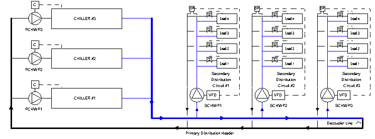
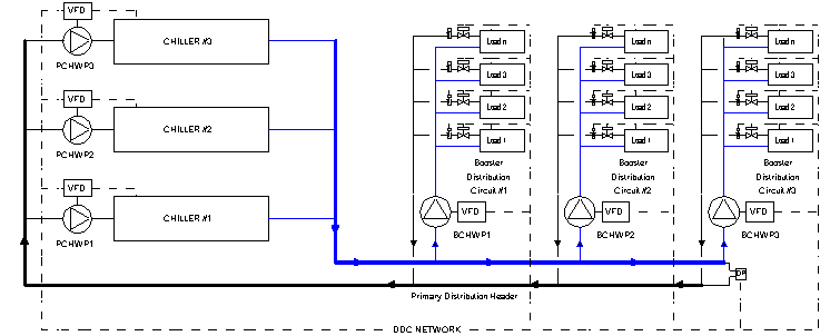
I've seen this before. I have the same perplexities. A variation can be a common manifold split in two with a balacing valve in the middle.
This is wrong

This is right

-
26-03-2007, 10:53 AM #4
Re: Common header
Hi NoNick, Your 1st schematic is exactly the case. Its almost like we have been looking at the same system.
I know for sure that the is no blanking plate in the header.
If the primary chilled water flow exceeds the demand, then the chillers would just cycle off when the return temeprature reaches SP.
Actually, looking at your schematic, mixing can only be a problem if one of the secondary demand circuits draws excessive flow. But this would be a design error. Yes?
Thanks for the schematics, with your permission, I would like to use them for a future course.
-
26-03-2007, 11:18 AM #5
Re: Common header
The two flows will never be the same. Only a magician can install a system with primary and three secondary having exactly the same flow.
Images are not mine. They have been linked from the internet.
The first schematic is very common in plants, but it has got a basic design flaw.
-
27-03-2007, 11:09 PM #6
Re: Common header
Try not to link to other sites, it puts extra load on there servers which is not fair, also some of them tend to change them for 'unwanted' content if they find out.Images are not mine. They have been linked from the internet.
Upload them to a picture hosting site like this...
http://www.tinypic.com/


Chillin
 IF AT FIRST YOU DON`T SUCCEED.
DESTROY ALL EVIDENCE THAT YOU TRIED!
and go get a cuppa


-
27-03-2007, 11:31 PM #7
Re: Common header
For a good magician call a commissioning engineer

I would say that both schematics have one basic fault and that is using two-port valves for the cooling coils. If three port diverting valves had been used then water flow rates would be more stable with improved conditions throughout.Brian - Newton Abbot, Devon, UK
Retired March 2015
-
28-03-2007, 07:58 AM #8
-
28-03-2007, 08:01 AM #9
-
28-03-2007, 11:07 AM #10
-
28-03-2007, 06:38 PM #11
Re: Common header
Because the pump is controlled by a VFD and via the DP feedback signal over both lines, you can use 2 ways valves in my opinion.
It's better to keep your mouth shut and give the impression that you're stupid than to open it and remove all doubt.
-
28-03-2007, 06:49 PM #12
-
28-03-2007, 11:21 PM #13
Re: Common header
I hate VFD. When the three are running at min speed, the chiller is just cooling itself and will soon stop abruptly.
Risk of falling leaving water temperature (possible freeze alarm) when chillers are caught running for minimum lead times and entering temperature below setpoint.
It's a no no for me.
-
30-03-2007, 04:53 AM #14
Re: Common header
There is no problem in either of the schemes suggested above. There will not be mixing in the first case, either, as the the fluid pressure in the secondary return can't be more than the fluid pressure in the decoupler line. Further, as the return fluid from AHU should go into chiller, there will not be any problem with mixing.
The first scheme dates back to the period when chiller manufacturers were arrogant about constant secondary refrigerant flow through chiller. The primary pumps are constant flow machines. During low loads, chilled water is bypassed through decoupler.
The second scheme is preferred with all variable flow chillers. A good capacity control at chiller end (for ex. a mix of guide vane and speed control of centrifugals) can facilitate variable primary flow and the problem due to freezing of evaporator tubes during low loads is minimized. I am not sure as to what kind of control signal is being used in the second scheme shown above. A DP can also be used (like the first scheme) for optimization of pumping power.
There is an excellent paper on the web about All variable flow chillers but I don't have the permission to post URLs at this instance.
-
30-03-2007, 09:13 AM #15
Re: Common header
Decoupler always bypass and mixing never happens, because cold water has a different density than warm water. Big manifolds with low water speed and no baffles worsen the separation and prevent the mixing.
So it is ok for just 0.05% of chillers now operating around the world.


