
Results 1 to 20 of 20
Thread: Discharge line failures
-
22-06-2009, 08:30 AM #1
 coolbear1 Guest
Discharge line failures
I took over the service and maintainence of a pair of refrigeration rack systems that have a history of discharge lines breaking at the compressor.
The racks were manufactured by Zero Zone and installed about three years ago.
They have Four 40 hp. Copeland (made by Bitzer)screws on the medium temp rack and Five 40 hp Copeland/Bitzer Screw compressors on the low temp rack.
The compressors are ridgid mounted to the frame, the discharge connections are four bolt flange with 1-5/8 brass flange adapters.
Starting at the compressor outlet, 1-5/8 Street x Street 90 degree copper elbows are welded to the flange adapter horizontally at the compressor, then turn down vertically to a ball valve that is between the ell, and a ridgid mounted 4 1/8 copper discharge manifold that runs bellow, horizontally, the lenth of the rack,
Both systems have had several failures, each in the same location, but on different compressors at random times over the life of the equipment.
The failures are always at the top of the weld, at the inlet of the ball valve, and the elbow.
I suspect metal fatigue, but I am dealing with the government, and needless to say, all they can do is have another meeting to try to decide who to blame and how not to spend any money.
I hope someone out there has had a similar problem that I might reference, to try to convence them to do something.
The thing belches 4 to 5 hundred pounds of 404A and 5 gallons of ester oil all over the motor room, and across the parking lot when it fails (usually in the middle of the night, or on a holiday), and I have to clean it up....twice so far.
They just have me reweld the same failed fitting, evacuate, change driers, charge it up and here we go again, just a time bomb, tick, tick.
I have pictures I can upload, if anyone is interested.
-
22-06-2009, 09:24 AM #2

 Moderator
Site Moderator : and general nice guy
Moderator
Site Moderator : and general nice guy


- Join Date
- Sep 2007
- Location
- Split Croatia
- Age
- 57
- Posts
- 6,151
- Blog Entries
- 6
- Rep Power
- 36
Re: Discharge line failures
From Bitzer aplication manual:
Unit construction and pipe layout
Due to the low vibration level and the
slight discharge gas pulsations, the
suction and discharge lines can normally
be built without using flexible
elements. The pipelines must however
be sufficiently flexible and not exert
any strain on the compressor. Critical
pipe section lengths should be avoided
(also dependent upon operating
conditions and refrigerant). Finally
large radius pipe bends should be
used no elbows.
Because of the high vapour density,
installations with R404A and
R507A are relatively critical
regarding resonant vibrations in
discharge gas lines and oil separators.
Vibration speeds can be
reduced significantly by fitting a
muffler (accessory) in the discharge
line after the compressor.
-
22-06-2009, 09:27 AM #3
VIP Poster
- Join Date
- Aug 2001
- Location
- UK
- Posts
- 1,046
- Rep Power
- 24
Re: Discharge line failures
.
Pictures of the pipe set-up and a close-up of the failed pipe may help to identify what the problem might be.
.
-
22-06-2009, 09:52 AM #4
Moderator
Site Moderator : and general nice guy
- Join Date
- Sep 2007
- Location
- Split Croatia
- Age
- 57
- Posts
- 6,151
- Blog Entries
- 6
- Rep Power
- 36
Re: Discharge line failures
Check this technical information:
http://www.bitzer.de/download/downlo...2.pdf&ccode=DELast edited by nike123; 22-06-2009 at 09:57 AM.
-
22-06-2009, 10:31 AM #5
Veteran Poster
- Join Date
- Sep 2008
- Location
- england
- Posts
- 427
- Rep Power
- 20
Re: Discharge line failures
I`ll go with Nike on this, any recip compressor on rigid mounts should be connected to the suction and delivery pipes by vibration absorbers as the heat generated and vibration can cause the copper pipes to work harden and eventually fail.
Regards,
Glenn
-
22-06-2009, 10:36 AM #6
Veteran Poster
- Join Date
- Sep 2008
- Location
- england
- Posts
- 427
- Rep Power
- 20
Re: Discharge line failures
Duuuuuh!!!
I should have gone to specsavers and read the post closer. Now I see they`re screw m/cs. I still reckon though, in light of the failures, fitting vibration aborbers would go a long way to solving this problem.
Now, where`s my nearest optician!!
-
22-06-2009, 12:45 PM #7
 VIP Poster
- Join Date
- Feb 2008
- Location
- adelaide sth.oz
- Posts
- 1,015
- Rep Power
- 19
Re: Discharge line failures
id go for a steel manifold.
mmm to beer or not to beer...........lets drink breakfast
-
22-06-2009, 01:46 PM #8
VIP Poster
- Join Date
- Aug 2008
- Location
- Baltics
- Age
- 62
- Posts
- 786
- Rep Power
- 16
Re: Discharge line failures
Hello Coolbear.
I am just wondering who would be accountable if, God save, people were hurt by the ***** outbursts. If manufacturer had made a gross mistake in project or assembly, would the 3 years since passed be a limit on his accountability?
-
22-06-2009, 03:11 PM #9
 VIP Poster
- Join Date
- Aug 2005
- Location
- USA
- Posts
- 5,302
- Rep Power
- 25
Re: Discharge line failures
While I have not seen this occur on a screw compressor rack I have seen multiple instances of this on racks using large recip compressors.
The energy in the discharge gas is very high. Pulsations, acoustics, etc.
Rewelding(?) fittings is not the answer.
Pictures would help to see what you see...If all else fails, ask for help.
-
22-06-2009, 03:53 PM #10
 Moderator
Site Moderator : and general nice guy
Moderator
Site Moderator : and general nice guy
- Join Date
- Sep 2003
- Location
- ISRAEL
- Age
- 72
- Posts
- 4,248
- Rep Power
- 46
Re: Discharge line failures
Had the same problem some years ago.
I have used 1.8M SS flexible pipes 100 Bar.
No problems ever since.
-
22-06-2009, 08:20 PM #11
 regular poster
- Join Date
- Jun 2007
- Location
- South Africa
- Age
- 66
- Posts
- 120
- Rep Power
- 17
Re: Discharge line failures
Hi coolbear1
First things first. Get rid of street elbows and use long radius elbows up to the manifold. Make sure discharge lines slope down to oil seperator to prevent oil/liquid traps.
From what you say it normally happens during night time or holidays, it tells me that you are sitting with liquid floodback at certain times. Make sure your evaporator superheat settings are correct, as well as suction superheat. Are there liquid coming back after defrost? Are the evaporator fans on at all times. Is there low loads without unloading the compressor?
Hydraulics occur in the discharge line when excessive liquid comes from the suction line through the screws and mixing with the oil in the discharge line! I have seen 1 5/8'' lines that look like 3 1/8" lines because of hydraulics.
-
23-06-2009, 02:51 AM #12
coolbear1 Guest
Re: Discharge line failures
Wow,
Thanks so much for the input, impressed is an understatement.
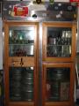
Here are the pictures I promised.
The crack is at the very top of the ball valve inlet and elbow weld.
You can actually see it if you click on it.
Thanks again for all the input.
-
23-06-2009, 03:40 AM #13
coolbear1 Guest
Re: Discharge line failures
I will atempt to answer some of your questions to the best of my ability.
But, if I miss any, they are all excellent, please remind me, and I will try.
The system controller is a CPC Reflecs RMCC.
Most of the evaporators, medium and low temp alike, are electric defrost with a typical typical defrost sequence.
All evaporators are independently controlled by a thermistor mounted at the evaporator.
Solenoid valves at each evaporator are controlled by the CPC controller when the programed set point is reached, the fans remain on.
The fans only stop during defrost and drip cycles.
Most circuits have EPR valves, except ones that operate at the rack pressure.
The only exception is the 40F, food prep. areas that are low air coils.
They are off cycle/air defrost, controlled by a timer and solenoid valve mounted at the coil, again the fans are not interupted.
The condenser is a Evapco, dual circuit evaporative type, with a single, two speed fan controlled by the CPC case controller.
The low temp system consists of one, smaller 28F room with four medium profile evaporators, and one larger -10F warehouse/freezer with one penthouse style evapoator on the roof.
-
23-06-2009, 04:14 AM #14
VIP Poster
- Join Date
- Aug 2005
- Location
- USA
- Posts
- 5,302
- Rep Power
- 25
Re: Discharge line failures
I'm not surprised. That is a very stiff (not flexible) connection. I'm not talking about a flex connector either. The piping is short and stiff. There is no flexibility in it.
Is this the only connection breaking?If all else fails, ask for help.
-
23-06-2009, 01:47 PM #15
VIP Poster
- Join Date
- Aug 2008
- Location
- Baltics
- Age
- 62
- Posts
- 786
- Rep Power
- 16
Re: Discharge line failures
Coolbear, what are the head temp-s reached at the comp-s? Is there some control for them?
-
23-06-2009, 07:08 PM #16
regular poster
- Join Date
- Jun 2007
- Location
- South Africa
- Age
- 66
- Posts
- 120
- Rep Power
- 17
Re: Discharge line failures
Coolbear1, your discharge lines are very short. Install a long radius elbow and move the discharge line's position more towards the left hand side and drop it in the main disharge line with a t-piece and reducing coupling. Even if it is in the opposite direction of where your oil seperator is.
I hate the big oil trap in the main discharge line! Oil can accumulate on low loads with only one compressor running or off cycle. When the load is high and the velocity steps up, it can create hydraulic pressure. Remember screw compressors thrive on oil and it is very thick compared to normal recip's oil.
I still need to know what the suction superheat is? Do you have a suction accumulator in the common suction line?
-
23-06-2009, 07:30 PM #17
VIP Poster
- Join Date
- Aug 2005
- Location
- USA
- Posts
- 5,302
- Rep Power
- 25
Re: Discharge line failures
I went back and looked at the original post again. Have another question for you...
Which means you've had similar failures in the middle of the discharge manifold on each rack??? Originally Posted by coolbear1
By any chance is the middle compressor being cycled off by the controller when the other compressors on either side of the compressor (that has the problem connection) are still running? If all else fails, ask for help.
-
24-06-2009, 04:37 AM #18
coolbear1 Guest
Re: Discharge line failures
I only have about 60 days of first hand history with this equipment.
People have come and gone in the three years since the building was constructed.
The current building manager thinks that this is the eighth failure, and that they are random.
The manufacturer of the rack seems to think that eight occurances may be accurate, and claims the failures are hydraulic in nature and have to do with power failures and the the back up generator.
I don't have enough information to support his theory.
The lines are not swollen at all, the crack is across the weld, not longitudinal to the pipe.
But this may not mean much given the fact that there is no pipe involved, only fittings, and a ball valve.
I may be wrong, but I lean toward metal fatigue.
But a combination of metal fatigue and hydraulics certainly could be involved.
There are suction accumulators, but not common to all of the compressors on the rack.
The compressors on a rack share the high side but not necessarily the low side.
The suction manifolds and regulators are connected to the compressors, then circuits grouped to them based on the suction pressure requirement, and BTU load.
The compressors are cycled on based on suction pressure only.
The discharge line manifold goes directly into a oil seperator/resevoir
(refer photo).
There are oil flow sensors, oil pressure controls, discharge pressure transducers, suction pressure transducers, discharge temperature thermistors, suction temperature transducers, current transducers.
-
24-06-2009, 12:26 PM #19
Veteran Poster
- Join Date
- May 2006
- Location
- India
- Age
- 74
- Posts
- 399
- Rep Power
- 18
Re: Discharge line failures
Temperature stress on rigid copper pipe could b one of the reason
-
25-06-2009, 06:05 AM #20
VIP Poster
- Join Date
- Feb 2008
- Location
- adelaide sth.oz
- Posts
- 1,015
- Rep Power
- 19
Re: Discharge line failures
pipe wall thickness and lack of support is not helping either,design of manifold came from a kindergarten,do yourself,the client and the enviroment a favour,rigid mount everything,have a manifold made from steel with swept entries,fix it down with more than a couple of strut clamps,problem solved.then run around and make sure everything is tuned to perfection.ah yes when you have new manifold made get them to fit the ball valves in the right way up,just for asthetics of course stuff the enviroment as little impact on it is the end result.
Last edited by lowcool; 25-06-2009 at 06:13 AM. Reason: ah yes their upside down
mmm to beer or not to beer...........lets drink breakfast

Similar Threads
-
Superheat and Subcooling
By Chunk in forum FundamentalsReplies: 42Last Post: 15-01-2011, 01:24 AM -
Oil in discharge line
By chillyblue in forum Trouble ShootingReplies: 18Last Post: 30-10-2008, 06:52 AM -
Oil Leak in NH3 Discharge Line Flange
By NH3LVR in forum IndustrialReplies: 9Last Post: 26-05-2007, 09:15 PM -
Exploded discharge line
By Peter_1 in forum IndustrialReplies: 1Last Post: 05-05-2004, 09:47 PM
