
Results 1 to 43 of 43
Thread: Coolpack help
-
17-01-2009, 04:08 PM #1

 VIP Poster


- Join Date
- Mar 2006
- Location
- Lancashire
- Posts
- 1,859
- Rep Power
- 28
Coolpack help
I have been learning about plotting multi evaporators on a ph chart today at college. However i'm still struggling a little bit to plot the correct place where the high stage evap meets the compressor.
My college tutor didn't seem sure where they should meet, so of course the class were none the wiser.
I've downloaded coolpack to try and plot it on there but i am being asked for DP evaporator, dp discharge line, dp suction line, dp condensor and dp liquid line but i dont know what "dp" stands for?
Can anyone help my quest for knowledge
The difference between genius and stupidity is that genius has its limits.
Marc
-
17-01-2009, 04:11 PM #2
 Registered User
I am just settling in to : RE
Registered User
I am just settling in to : RE
- Join Date
- Mar 2006
- Location
- Merate (LC) - Italy
- Age
- 52
- Posts
- 2,549
- Rep Power
- 24
Re: Coolpack help
delta P = pressure drop
-
17-01-2009, 04:23 PM #3
VIP Poster
- Join Date
- Mar 2006
- Location
- Lancashire
- Posts
- 1,859
- Rep Power
- 28
Re: Coolpack help
Ahh ok. At college i had only been taught that i need to enter the Evap temp, condensing temp, the discharge temp, the liquid temp and the suction temps. No mention of pressure drops....
Is there no where on there that i can draw a ph chart using the above figures rather than pd?The difference between genius and stupidity is that genius has its limits.
Marc
-
17-01-2009, 05:07 PM #4
 Moderator
Site Moderator : and general nice guy
Moderator
Site Moderator : and general nice guy
- Join Date
- Sep 2007
- Location
- Split Croatia
- Age
- 57
- Posts
- 6,151
- Blog Entries
- 6
- Rep Power
- 36
Re: Coolpack help
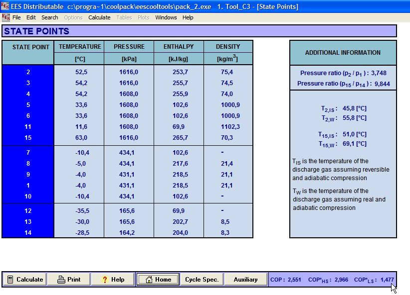
You have in Cool Pack State Points tab where you could see pressure difference between two state points. That is your pd. Originally Posted by marc5180

-
17-01-2009, 05:45 PM #5
 Veteran Poster
- Join Date
- Feb 2008
- Location
- Norway
- Age
- 57
- Posts
- 446
- Rep Power
- 17
Re: Coolpack help
Is it a one compressor system with one common suction pressure? Originally Posted by marc5180
-
17-01-2009, 05:52 PM #6
VIP Poster
- Join Date
- Mar 2006
- Location
- Lancashire
- Posts
- 1,859
- Rep Power
- 28
Re: Coolpack help
yes it is a 1 compressor system with one common suction Originally Posted by SteinarN
The difference between genius and stupidity is that genius has its limits.
Marc
-
17-01-2009, 05:54 PM #7
Veteran Poster
- Join Date
- Feb 2008
- Location
- Norway
- Age
- 57
- Posts
- 446
- Rep Power
- 17
Re: Coolpack help
Do you have the same evaporating pressure in all evaporators or do you have some evaporator pressure regulator in the system? Originally Posted by marc5180
-
17-01-2009, 05:58 PM #8
VIP Poster
- Join Date
- Mar 2006
- Location
- Lancashire
- Posts
- 1,859
- Rep Power
- 28
Re: Coolpack help
Nike, is that diagram a single compressor and 2 evaporators? From the looks of it looks like 2 compressors, 1 condensor and 2 evaporators.
Why is the 2 lines leading down from the condensor, points 6-7 and 11-12?
I understand point 5 to be liquid line temp, but what is 6 and 11?The difference between genius and stupidity is that genius has its limits.
Marc
-
17-01-2009, 05:59 PM #9
VIP Poster
- Join Date
- Mar 2006
- Location
- Lancashire
- Posts
- 1,859
- Rep Power
- 28
Re: Coolpack help
no the evap pressures are different -10 and -40 with an EPR Originally Posted by SteinarN
Last edited by marc5180; 17-01-2009 at 06:19 PM.
The difference between genius and stupidity is that genius has its limits.
Marc
-
17-01-2009, 06:22 PM #10
Veteran Poster
- Join Date
- Feb 2008
- Location
- Norway
- Age
- 57
- Posts
- 446
- Rep Power
- 17
Re: Coolpack help
Well, this solution gives a system with a horrible efficiency Originally Posted by marc5180
")
But to draw this system, start with the low pressure evaporator and draw this complete system with the condenser, but leave the line for the compressor at this point. When this is done draw the evaporator line for the high pressure evaporator, connect the left end of this line to the vertical line expressing the exv at the low pressure evaporator, draw the right end of this line to where it meets the temperature line for the evaporator outlet at correct superheat. Then draw a vertical line from the right end of the high pressure evaporator line and down to the pressure line for the low pressure evaporator. This vertical line express the suction pressure regulator for the high pressure evaporator. Draw a short horizontal line to connect this newly drawn vertical line with the right end of the evaporator line for the low pressure evaporator. The start line for the compressor suction is somewhere on this short horizontal line and exactly where depends on the mass flow ratio between the low pressure and the high pressure evaporator. If the mass flow is equal in the low and high evaporator then this point is roughly on the middle on this short line. Now draw the compressor line and conect it to the right end of the condenser line and you are done.
-
17-01-2009, 06:39 PM #11
Veteran Poster
- Join Date
- Feb 2008
- Location
- Norway
- Age
- 57
- Posts
- 446
- Rep Power
- 17
Re: Coolpack help
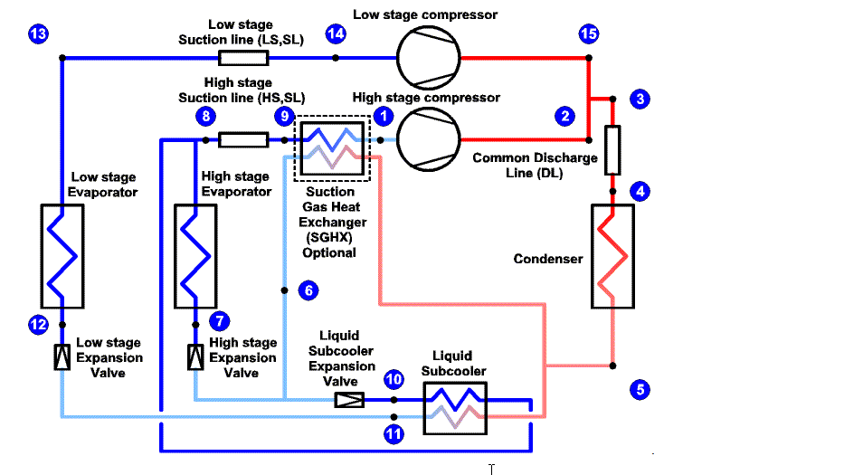
Yep, two compressors, two evaporators and one condenser. Originally Posted by marc5180
Point/line 6 and 7 is the inlet and outlet of the high side exv.
Point/line 6 and 11 is an evaporator connected to suction of the high side compressor. This evaporator cools the liqiud to the low side exv.
Point/line 11 and 12 is the inlet and outlet of the low side exv.
-
17-01-2009, 06:47 PM #12
VIP Poster
- Join Date
- Mar 2006
- Location
- Lancashire
- Posts
- 1,859
- Rep Power
- 28
Re: Coolpack help
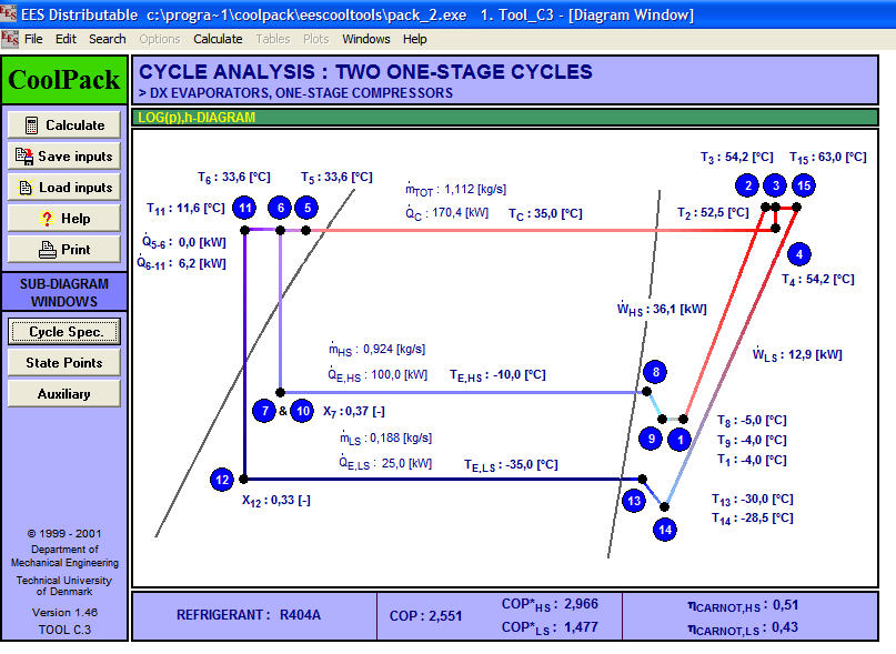
OK so point 12 to 13 is low side evap
point 10 to 8 is high side evap.
I see that point 14 to 15 is a compressor as is point1 to 2
but... i haven't been taught about points 13 to 14 and 8 to 9 ( this must be superheat?)
What about 9 to 1? and also 3 to 4?
I appreciate you helping me out like thisThe difference between genius and stupidity is that genius has its limits.
Marc
-
17-01-2009, 06:57 PM #13
Veteran Poster
- Join Date
- Feb 2008
- Location
- Norway
- Age
- 57
- Posts
- 446
- Rep Power
- 17
Re: Coolpack help
13 to 14 is the heat added to the suction line outside the freezer and also the pressure loss in the suction line. Originally Posted by marc5180
8 to 9 is the same for the high side system.
9 to 1 is the suction gas/liquid line heat exchanger, but in this case there is none. Therefore the temp at point 9 and 1 is the same. It's only the graphic drawing showing theese points as two different poins. In real they are on top of each other in this case when there is no heat exchanger.
3 to 4 is the pressure loss in the HP line from the compressors to the condenser and the pressure loss in the condenser.
-
17-01-2009, 07:00 PM #14
VIP Poster
- Join Date
- Mar 2006
- Location
- Lancashire
- Posts
- 1,859
- Rep Power
- 28
Re: Coolpack help
I think i have it, could you show me what it should look like like on a ph chart possibly ( i know it's a big ask) because this isn't what i have been taught today at college. Originally Posted by SteinarN
I think i have it right but i want to be sure.The difference between genius and stupidity is that genius has its limits.
Marc
-
17-01-2009, 07:06 PM #15
Veteran Poster
- Join Date
- Feb 2008
- Location
- Norway
- Age
- 57
- Posts
- 446
- Rep Power
- 17
Re: Coolpack help
It's not possible to draw this system in CoolPack. The reason is probably your system is so horribly inefficient that this variant isn't included in the options. No one would design a system like that today in theese energy conservation times. Originally Posted by marc5180
What I have explained here is a very detailed expression of a real system. What you have been thaught is a simplified expression of the same system. That is to ignore the pressure loss in the discharge and suction lines and ignore the heat flux into the suction lines outside the coold rooms.
Maybe you could take a picture of your drawing and post it here?
-
17-01-2009, 07:30 PM #16
VIP Poster
- Join Date
- Mar 2006
- Location
- Lancashire
- Posts
- 1,859
- Rep Power
- 28
Re: Coolpack help
Yes thats a good idea, i will set up my camera and then post it here. I would like to be sure that the way it is plotted is correct.
The difference between genius and stupidity is that genius has its limits.
Marc
-
17-01-2009, 07:34 PM #17
Moderator
Site Moderator : and general nice guy
- Join Date
- Sep 2007
- Location
- Split Croatia
- Age
- 57
- Posts
- 6,151
- Blog Entries
- 6
- Rep Power
- 36
Re: Coolpack help
It is 2 compressors. 6-7 is suction gas heat exchanger to HT evaporator line and 11-12 is liquid subcooler to LT evaporator line. For explanation see help of tool C3. Originally Posted by marc5180
Last edited by nike123; 17-01-2009 at 07:48 PM.
-
17-01-2009, 07:53 PM #18
VIP Poster
- Join Date
- Mar 2006
- Location
- Lancashire
- Posts
- 1,859
- Rep Power
- 28
Re: Coolpack help
Thanks Nike,
Below are the temperatures that i had to plot the chart;
A1) Low temp evaporating temperature @ -30*C
B1) Suction temperature @ -20*C
A2) High temp evaporating temperature @ -5*C
B2) Cant remember what this was, think it was superheat?
C) Discharge temp @ 65*C
D) Liquid line temp @ 30*C
 The difference between genius and stupidity is that genius has its limits.
Marc
-
17-01-2009, 08:09 PM #19
Veteran Poster
- Join Date
- Feb 2008
- Location
- Norway
- Age
- 57
- Posts
- 446
- Rep Power
- 17
Re: Coolpack help
B2 is evaporator outlet temp. Originally Posted by marc5180
The line from B2 to B1 shall be absolutely vertical. As it's now the bottom of the line is to far to the left. Draw it vertical down until it reach the pressure line for the low side evaporator. If you assume -20C low side evaporator outlet the start line for compressor suction shall be between this -20C point and the point where the vertical line from the high side evaporator intersects the pressure line for the low side evaporator.
Remove the needless parts of the lines for better clarity.
-
17-01-2009, 08:14 PM #20
Moderator
Site Moderator : and general nice guy
- Join Date
- Sep 2007
- Location
- Split Croatia
- Age
- 57
- Posts
- 6,151
- Blog Entries
- 6
- Rep Power
- 36
Re: Coolpack help
Also, in refrigeration utilities for log(p)-h diagram instead of dp you could (as input) use temperature diference by choosing K instead of Bar as unit.
-
17-01-2009, 09:30 PM #21
VIP Poster
- Join Date
- Mar 2006
- Location
- Lancashire
- Posts
- 1,859
- Rep Power
- 28
Re: Coolpack help
How could the line be vertical though with the temperatures that i have been given? the line has to go to the left slightly. Originally Posted by SteinarN
I've uploaded 2 more plotted charts to see which way it should be filled in, is it ph chart A or B?

 The difference between genius and stupidity is that genius has its limits.
Marc
-
17-01-2009, 09:38 PM #22
VIP Poster
- Join Date
- Mar 2006
- Location
- Lancashire
- Posts
- 1,859
- Rep Power
- 28
Re: Coolpack help
Or should it be done like this?
 The difference between genius and stupidity is that genius has its limits.
Marc
-
17-01-2009, 10:00 PM #23
Veteran Poster
- Join Date
- Feb 2008
- Location
- Norway
- Age
- 57
- Posts
- 446
- Rep Power
- 17
Re: Coolpack help
The line must be vertical. If it's not then you are violating physical laws. Dont care on what temperatures you have been given except if you have been given an outlet temp for the high side evaporator.
The compressor suction temperature may be roughly somewhere between the low temp evaporator outlet and the high temp evaporator outlet depending on the relative flow rate between thse two evaporators.
A is completely wrong. B is wrong also.
If you hav been given a B2 temp, then use this temp for the B2 point. Then draw an exactly vertical line down from B2.
Draw the low side evaporator line to the right where it intersects with the vertical line from B2.
The start point for the compressor suction shall be somewhere on the superheated part on the low side evaporator line. That is if you have say 7C superheat on the low side evaporator, this will give an evaporator outlet of -23C. Start the compressor line somewhere between -23C and the rightmost end of the low side evaporator line. You can start at -20C. You then get a short segment of line to the right of the compressor suction where it connects with the vertical line from B2. This will determine a much larger mass flow in the low side evaporator than in the high side evaporator. If the line started at say -15C that would determine the mass flow in the low side evaporator to be not so much larger than the high side evaporator.
-
17-01-2009, 10:05 PM #24
Veteran Poster
- Join Date
- Feb 2008
- Location
- Norway
- Age
- 57
- Posts
- 446
- Rep Power
- 17
Re: Coolpack help
The last picture is also wrong. The vertical line from B2 must go vertically down to the level of the low side evaporator line in one straight segment. The low side line then must go to the right until it reach the end point of the vertical line from B2.
-
17-01-2009, 10:41 PM #25
VIP Poster
- Join Date
- Mar 2006
- Location
- Lancashire
- Posts
- 1,859
- Rep Power
- 28
Re: Coolpack help
Ok so i have now drawn a vertical line down from B2 down, from here my low temp evap line has met B2 vertical line, as shown below;
I still can't understand where C joins to
 The difference between genius and stupidity is that genius has its limits.
Marc
-
17-01-2009, 10:57 PM #26
Veteran Poster
- Join Date
- Feb 2008
- Location
- Norway
- Age
- 57
- Posts
- 446
- Rep Power
- 17
Re: Coolpack help
Line from C should join the low pressure evaporator line at say -20C in the superheated region, not join the high pressure evaporator line as it does in your last drawing. Originally Posted by marc5180
Edit: If A2 is at -20C, then you can draw the compressor line from C to A2.Last edited by SteinarN; 17-01-2009 at 10:59 PM.
-
17-01-2009, 11:05 PM #27
VIP Poster
- Join Date
- Mar 2006
- Location
- Lancashire
- Posts
- 1,859
- Rep Power
- 28
Re: Coolpack help


Last edited by marc5180; 17-01-2009 at 11:08 PM.
The difference between genius and stupidity is that genius has its limits.
Marc
-
17-01-2009, 11:28 PM #28
Veteran Poster
- Join Date
- Feb 2008
- Location
- Norway
- Age
- 57
- Posts
- 446
- Rep Power
- 17
Re: Coolpack help
Now you have it.... I think. Is the line from down from B2 vertical, that is paralell to the constant enthalpy line, or is it paralell to the constant temperature line in the superheated area in the No2 picture? It should be paralell to the constant enthalpy line.
As it is drawn now the capasity of the low side evaporator is much higher than in the high side evaporator. This is a horribly inefficient system, but it's what you where asked to draw.
-
17-01-2009, 11:37 PM #29
VIP Poster
- Join Date
- Mar 2006
- Location
- Lancashire
- Posts
- 1,859
- Rep Power
- 28
Re: Coolpack help
Yes it's paralell to the constant enthalpy line, i must have took the photograph on a slight angle, which makes the line look like it slopes to one side.
My college tutor just made tempertures up quickly, just so we got used to plotting them i think. However what he taught us didn't look like the above.The difference between genius and stupidity is that genius has its limits.
Marc
-
17-01-2009, 11:42 PM #30
Veteran Poster
- Join Date
- Feb 2008
- Location
- Norway
- Age
- 57
- Posts
- 446
- Rep Power
- 17
Re: Coolpack help
This is the corect chart for the system you have explained when we not tak into acount pressure loss in the lines and heat loss in the suction lines. Also the compressor efficiency may be wrong, but thats your tutors problem since he gave the value for dicharge temperature.
-
17-01-2009, 11:51 PM #31
VIP Poster
- Join Date
- Mar 2006
- Location
- Lancashire
- Posts
- 1,859
- Rep Power
- 28
Re: Coolpack help
I will have many questions to ask him next week about this.
Thanks for spending so much time trying to explain it to me, really appreciate it.The difference between genius and stupidity is that genius has its limits.
Marc
-
17-01-2009, 11:52 PM #32
Veteran Poster
- Join Date
- Feb 2008
- Location
- Norway
- Age
- 57
- Posts
- 446
- Rep Power
- 17
Re: Coolpack help
You'r welcome

-
24-01-2009, 01:39 PM #33
VIP Poster
- Join Date
- Mar 2006
- Location
- Lancashire
- Posts
- 1,859
- Rep Power
- 28
Re: Coolpack help
Hi, i went back to my tutor today and explained what you said about the line from the high stage evaporator having to be drawn vertically drawn and he disagrees totally.
He explained that it is a mixing process and not an expansion process as it leaves the EPR so the line cannot be vertical.The difference between genius and stupidity is that genius has its limits.
Marc
-
24-01-2009, 04:15 PM #34
 Senior Poster
- Join Date
- Feb 2007
- Location
- north west
- Age
- 36
- Posts
- 243
- Rep Power
- 18
Re: Coolpack help
i can see this is going to be an interesting post!!!!!
-
24-01-2009, 05:20 PM #35
Moderator
Site Moderator : and general nice guy
- Join Date
- Sep 2007
- Location
- Split Croatia
- Age
- 57
- Posts
- 6,151
- Blog Entries
- 6
- Rep Power
- 36
Re: Coolpack help
Maybe this patent drawing could be of help!
-
24-01-2009, 06:29 PM #36
Veteran Poster
- Join Date
- Feb 2008
- Location
- Norway
- Age
- 57
- Posts
- 446
- Rep Power
- 17
Re: Coolpack help
It is indeed an expansion process taking place in the EPR exactly similar to the expansion process in a TEV. The inlet and outlet pressure is different while the specific entalphy is the same. The specific enthalphy line is the vertical line in the log ph chart. Therefore a process line involving a change in some properties but where the entalphy is NOT changing cannot be any other than vertical. Originally Posted by marc5180
The mixing process is the short horisontal line between the low pressure evaporator line right end coresponding to low side evaporator outlet and the lower end of the vertical line from the high side evaporator.
Where on this line the compressor line starts is determined on the relative mass flow between the high side evaporator and the low side evaporator. If the mass flow in the high side evaporator is much larger than the low side evaporator, then the compressor line should start to the right for A2, near the end point for the vertical line from the high side evaporator. If the opposite is true then the compressor line shall start where you have drawn it.
Your tutor defined the compressor suction to be -20C, therefore you have drawn it where you have and it is completely correct!
A small mass flow of say -8C gas from the EPR mix with a large flow of say -23C gas from the low side evaporator to give a mix of -20C gas entering the compressor.
Your tutor is wrong and should be educated by you in this case!
Last edited by SteinarN; 24-01-2009 at 09:36 PM.
-
24-01-2009, 06:40 PM #37
Veteran Poster
- Join Date
- Feb 2008
- Location
- Norway
- Age
- 57
- Posts
- 446
- Rep Power
- 17
Re: Coolpack help
You should have three different points on the low pressure evaporator line to make the chart easier to interpret.
There should be one point, say at -23C indicating the gas leaving the low side evaporator. Another mark at -20C where the compressor line starts. You already have this mark, A2, specified by your tutor. The last mark is the low point of the vertical line from the high side evaporator, this point express the condition at the outlet of the EPR and is on the same pressure line as your low side evaporator. The vertical line from the high side evaporator is expressing the EPR in exactly same way as the vertical line at the left end of your chart is expressing the TEV.Last edited by SteinarN; 24-01-2009 at 09:37 PM.
-
24-01-2009, 08:46 PM #38
regular poster
- Join Date
- Aug 2007
- Location
- Russia
- Posts
- 138
- Rep Power
- 21
Re: Coolpack help
I also have a question about Coolpack.
Lets say we need to estimate a cooling capacity of the unit. Let it will be a direct expansion unit with 1 system. (1 comp, 1 evap. and 1 cond.) The datum we have is
-compressor displacement
-evap. pressure
-cond. pressure
-evap. superheat
-cond. subcooling
-refrigerant type
Is it enough to do the task with the Coolpack? How it may be done?
-
24-01-2009, 09:18 PM #39
Moderator
Site Moderator : and general nice guy
- Join Date
- Sep 2007
- Location
- Split Croatia
- Age
- 57
- Posts
- 6,151
- Blog Entries
- 6
- Rep Power
- 36
Re: Coolpack help
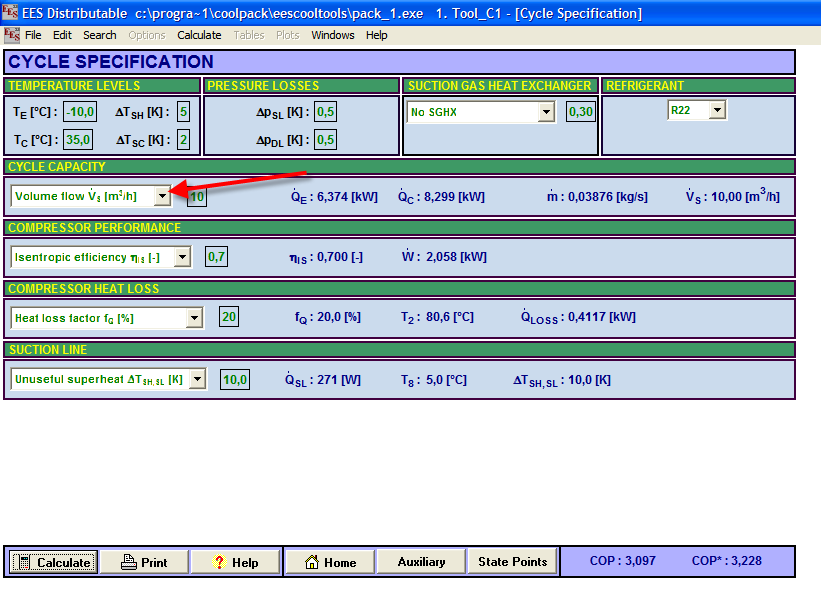
Yes it is, just select instead of "cooling capacity" "volume flow" in cycle capacity tab, input your displacement (and other values you have) and hit calculate. Originally Posted by narkom
Blue numbers are calculated values and green numbers are your inputs.
-
25-01-2009, 11:28 AM #40
regular poster
- Join Date
- Aug 2007
- Location
- Russia
- Posts
- 138
- Rep Power
- 21
Re: Coolpack help
Thank you very much!
-
29-01-2009, 08:54 PM #41
Veteran Poster
- Join Date
- Feb 2008
- Location
- Norway
- Age
- 57
- Posts
- 446
- Rep Power
- 17
Re: Coolpack help
Any update on your progress with your tutor, marc?
-
31-01-2009, 02:22 AM #42
Guayoyo Guest
Re: Coolpack help
Sure Mark, DP stands for pressure drop in each part or equipment of the system. I hope this help. If you need further asistance, please let me know Originally Posted by marc5180
-
31-01-2009, 10:28 PM #43
VIP Poster
- Join Date
- Mar 2006
- Location
- Lancashire
- Posts
- 1,859
- Rep Power
- 28
Re: Coolpack help
Thanks SteinarN.
Last edited by marc5180; 05-02-2009 at 08:09 PM.
The difference between genius and stupidity is that genius has its limits.
Marc


Similar Threads
-
Coolpack
By Mur24 in forum Tools and CalculatorsReplies: 13Last Post: 28-05-2011, 11:30 PM -
Coolpack
By lloydjosang in forum Tools and CalculatorsReplies: 2Last Post: 06-04-2008, 11:05 AM -
CoolPack Cycle Input
By Bones in forum TrainingReplies: 4Last Post: 02-12-2003, 09:18 AM -
Coolpack
By Koudijs in forum TrainingReplies: 7Last Post: 03-01-2003, 10:15 PM
