
Results 1 to 33 of 33
Thread: Refriferation cycle question
-
25-03-2008, 12:00 AM #1

 improving poster

- Join Date
- Mar 2008
- Location
- OZ
- Age
- 38
- Posts
- 23
- Rep Power
- 0
Refriferation cycle question
Hi all,
I have been given this question fro my subject and need to solve it. It is ment to introduce us to heat transfer and fluid flow considerations in the design of shell and tube heat exchangers. The question is:
A hermetic compressor, isentropic efficiency is 63%, receives R22 vapour from an evap where the Tsat is -5 degrees C. The vapour leaves the evap with 15 deg C of superheat and travels to the comp through a well insulated pipe. The cooling capacity achieved in the evap is 9.7 kW (so this is Qevap right??) The condenser Tsat is 42 deg C. Refrigerant leaves the condenser as liquid sub cooled by 2 deg C, and travels directly to a throttle valve with out change in temp.
A) sketch the cycles on the pressure enthalpy chart for isentropic compressor and actual unit (i know what the general shape should be, but how is the actual diff to isentropic, and what locations of P and h should i have)
B) determine the mass flow rate of the refrigerant through the evaporator
(can i use Qevap = m(h1 - h3)???)
C) Determine the heat rejection rate through the condenser, when receiving the vapour from the actual compressor
OK now i know these may seem like simple questions but i am relatively new to this and our teacher has pretty much thrown us in the deep end with minimal instruction. I don't want the answers i would just like some assistance and instruction on how to tackle this question, so i can learn for the future.
Thanks everyone, any help would be awesome.
Cheers
-
25-03-2008, 01:03 AM #2
 VIP Poster
- Join Date
- Oct 2006
- Location
- England
- Posts
- 1,843
- Rep Power
- 21
Re: Refriferation cycle question
 Originally Posted by ozmecheng

I am torn between helping you and telling you to do the work your self.
So I will give you a clue.
http://www.et.web.mek.dtu.dk/Coolpack/UK/download.html
Coolpack is your friend.
Cheers taz.
-
25-03-2008, 01:03 AM #3
 VIP Poster
- Join Date
- Aug 2005
- Location
- USA
- Posts
- 5,302
- Rep Power
- 25
Re: Refriferation cycle question
Looks like you have your work cut out for you if the teacher just throws you to the sharks.

First things first...
Your liquid enthalpy will be determined by:
- condenser Tsat is 42°C - 2K subcooling = 40°C
- Therefore you need to find the liquid enthalpy at 40°C at the pressure in the condenser (assuming the pressure is equal to the saturation temperature of 42°C).
Is the superheat picked up in the evaporator useful? In other words are you using the vapor enthalpy where Tsat is -5°C or at the evaporating pressure equal to -5°C at an actual temperature of +10°C?
If you use the superheated condition for the vapor enthalpy the mass flow will be lower due to a greater delta h. This will also affect your third question.
That should keep you busy for awhile....If all else fails, ask for help.
-
25-03-2008, 01:20 AM #4
VIP Poster
- Join Date
- Aug 2005
- Location
- USA
- Posts
- 5,302
- Rep Power
- 25
Re: Refriferation cycle question
taz,
I'll admit I am not a fan of using software to teach.
Sure the student might get a correct answer, but I doubt they will realize how they got that answer.
I don't mean to rain on your parade.... but I guess I did, didn't I? If all else fails, ask for help.
-
25-03-2008, 04:22 AM #5
improving poster
- Join Date
- Mar 2008
- Location
- OZ
- Age
- 38
- Posts
- 23
- Rep Power
- 0
Re: Refriferation cycle question
thanks fellas, yer iceman im being fed to the after darks as we speak lol. Yes i have coolpack, it gave me some decent tables and diagrams cos the ones he gave us were imperial and you couldn't read them anyway.
Im not sure about the super heated part in the evap but i get what you mean. He hasn't given us superheat tables but usually does so is that any give away.
Ok so one typical refrig P-h diagram we have
Point 1 - entering the comp, unsure of conditions here so cant really do much.
Point 2 - superheated vapour leaving comp, I need point 1s conditions to find this dont i?
Point 3 - subcooled liquid leaving cond at 42 deg C, sub cooled to 40 deg C which corresponds to a pressure of 104.95 kPa, Hf = 155.4.
point 4 - Liquid vapor mix entering evap, because the TX valve is constant enthalpy, here Hf = 155.4 correct?
Ok so where does this leave me.
thanks again for everyones help, i do not want to repeat this subject lol
cheers
-
25-03-2008, 06:21 AM #6
Veteran Poster
- Join Date
- Feb 2008
- Location
- Norway
- Age
- 57
- Posts
- 446
- Rep Power
- 17
Re: Refriferation cycle question
Hi ozmecheng.
You said in your first post the gas leaves the evaporator at 15 degrees superheat and flows through a well insulated pipe. You havent got any information on any non useful superheat in lets say the suction line. I guess you could assume 15 degrees useful superheat at compressor inlet.
You then have the point 1, compressor inlet condition. You have to get the exact specific entrophy at that point. Find the point on the pressure line coresponding to 42cond, where you have that exact same entrophy as in point 1. The difference in enthalphy at those two points is the compressor work at 100% isentropic efficiency.
How to find real compressor work? You have to do a simple division using 0,63 and the difference in enthalphy in point 1 and 2. I guess you figure it out.
-
25-03-2008, 06:49 AM #7
improving poster
- Join Date
- Mar 2008
- Location
- OZ
- Age
- 38
- Posts
- 23
- Rep Power
- 0
Re: Refriferation cycle question
ok ta for that steiner, but i am a little confused, you say i have compressor inlet condition. so i assume that there is 15 deg C superheat at comp inlet, at a degrees of 10C. But when i want to get the Hg value for here, were do i look cos we are assuming that the vapor is super heated but i dont have superheat tables. so i need the condition at point one inlet to comp (Hg and Sg) then to get to comp outlet at point 2, i follow the constant entropy line up to the same pressure as 42 deg C. Correct?
Thanks again, i really want to try and get ontop of this stuff
-
25-03-2008, 07:24 AM #8
Veteran Poster
- Join Date
- Feb 2008
- Location
- Norway
- Age
- 57
- Posts
- 446
- Rep Power
- 17
Re: Refriferation cycle question
Have you got a log P-h chart from your teacher? You find your data there. You said you have coolpack. You have a powerful tool there also. You can print out a log P-h chart or tables as you will. You can also download tables from Du Pont.
http://refrigerants.dupont.com/Suva/...pdf/k05736.pdf
-
25-03-2008, 07:27 AM #9
Veteran Poster
- Join Date
- Feb 2008
- Location
- Norway
- Age
- 57
- Posts
- 446
- Rep Power
- 17
Re: Refriferation cycle question
Yes, but this is at 100% isentropic efficiency. You have to corect for the real compressor efficiency of 63%. Se my post above. Originally Posted by ozmecheng
Take the difference in enthalphy between point 1 and point 2 assuming 100% efficiency. Divide that difference by 0,63. This result is the real compressor work. The sum of the real compressor work enthalphy and the enthalphy in point 1 is the real enthalphy in point 2. You then have the enthalphy in point 2 at 63% isentropic efficiency assuming no heat loss from the compressor.Last edited by SteinarN; 25-03-2008 at 07:36 AM.
-
25-03-2008, 07:36 AM #10
improving poster
- Join Date
- Mar 2008
- Location
- OZ
- Age
- 38
- Posts
- 23
- Rep Power
- 0
Re: Refriferation cycle question
yes i got tables and diagram off cool pack, very useful tool indeed. Its the superheat component that im concerned about. so is the Hg at -5 deg C plus the Hg of superheated 15 deg C the same as just Hg at 10 deg C and corresponding pressure of 10 deg C.
Therefore do i simply just start on the p-h diagram at 10 deg C and follow the constant enthalpy curve up to the respective pressure of 42 deg C.
cheers
-
25-03-2008, 07:48 AM #11
Veteran Poster
- Join Date
- Feb 2008
- Location
- Norway
- Age
- 57
- Posts
- 446
- Rep Power
- 17
Re: Refriferation cycle question
No. You follow the pressure line at -5sat out to the right where it crosses the near vertical line for +10 degres temperature. This is your point 1. This is in the superheated area of the chart. Originally Posted by ozmecheng
Last edited by SteinarN; 25-03-2008 at 07:51 AM.
-
25-03-2008, 08:56 AM #12
improving poster
- Join Date
- Mar 2008
- Location
- OZ
- Age
- 38
- Posts
- 23
- Rep Power
- 0
Re: Refriferation cycle question
ah awesome, thanks mate i fianlly get it, why the hell didn't my teacher just say this in class. Sheees!! hes going on about all this other crap with charts and adding pressures bla bla the diamgram is so much easy to work with than a chart
so at -5 deg C i go left til i hit the 10 deg C constant temp line. this interescts with the s = 1.80 constant entropy line which i will follow up (for my isentropic comp) to the pressure line corresponding to 42 deg C.
sound Correct?
-
25-03-2008, 09:23 AM #13
improving poster
- Join Date
- Mar 2008
- Location
- OZ
- Age
- 38
- Posts
- 23
- Rep Power
- 0
Re: Refriferation cycle question
ok heres something fishy, when i plot this cycle in cool pack (which is a really wicked program by the way) i put in evap temp as -5 deg C and super heat as 15 deg C. it does whats expected except it goes right towards the constant temp lines but stops at the 15 deg C, not the 10 deg C line as you've said previosly. Is this the program or what
-
25-03-2008, 03:01 PM #14
Veteran Poster
- Join Date
- Feb 2008
- Location
- Norway
- Age
- 57
- Posts
- 446
- Rep Power
- 17
Re: Refriferation cycle question
When you specify the data in the program, do you enter the superheat in C or K? You have to enter it in K. If it is C, then it is the compressor suction temperature, that is 15C as you says the program draws. If it is 15K, then it is 15 degres superheat, that is -5C+15K=10C suction temperature. Originally Posted by ozmecheng
-
25-03-2008, 03:06 PM #15
Veteran Poster
- Join Date
- Feb 2008
- Location
- Norway
- Age
- 57
- Posts
- 446
- Rep Power
- 17
Re: Refriferation cycle question
Yes, correct for a compressor at 100% isentropic efficiency. But as you see, point 2 is farther to the right when you specify an isentropic efficiency less than 1. Originally Posted by ozmecheng
-
25-03-2008, 07:19 PM #16
VIP Poster
- Join Date
- Aug 2005
- Location
- USA
- Posts
- 5,302
- Rep Power
- 25
Re: Refriferation cycle question
It seems this is moving along very nicely.
 SteinarN is doing a nice job of explaining this.
ozmecheng, don't worry about needing superheat tables. All of the information you need is on the P-H diagram.
If you assume the superheat is useful, you plot the actual temperature at the evaporating pressure. You will find this point to the right of the dew point line on the P-H diagram (in the superheated zone). The bubble point line is the one on the left side of the diagram. Any point to the left of the bubble point curve is subcooled.
The constant entropy line only applies when the isentropic (constant entropy) efficiency is 100%. So, the deviation from perfect compression causes the curvature of the line to shift to the right somewhat.If all else fails, ask for help.
-
25-03-2008, 07:36 PM #17
Veteran Poster
- Join Date
- Feb 2008
- Location
- Norway
- Age
- 57
- Posts
- 446
- Rep Power
- 17
Re: Refriferation cycle question
Well, I've been sort of hijacking the explanation in this thread from you, Iceman. You was not early enough up in the morning. Originally Posted by US Iceman

-
25-03-2008, 07:52 PM #18
VIP Poster
- Join Date
- Aug 2005
- Location
- USA
- Posts
- 5,302
- Rep Power
- 25
Re: Refriferation cycle question
This is why the time zones work against me. I have to sleep sometime! On the other hand, the answers get furnished very quickly because of the time zones. Originally Posted by SteinarN
 If all else fails, ask for help.
-
25-03-2008, 07:56 PM #19
VIP Poster
- Join Date
- Aug 2005
- Location
- USA
- Posts
- 5,302
- Rep Power
- 25
Re: Refriferation cycle question
ozmecheng,
I forgot to add some thoughts on the suction line.
When you list the assumptions used for the answer you should state the suction line is considered as a control volume. In effect, you are saying no heat is added or removed form the suction line. Therefore, the superheat is constant to the compressor suction.If all else fails, ask for help.
-
25-03-2008, 11:08 PM #20
improving poster
- Join Date
- Mar 2008
- Location
- OZ
- Age
- 38
- Posts
- 23
- Rep Power
- 0
Re: Refriferation cycle question
yes iceman we are progressing at a good rate, much faster than i do in class anyway lol. Thanks to stienar who has been very helpful Originally Posted by US Iceman
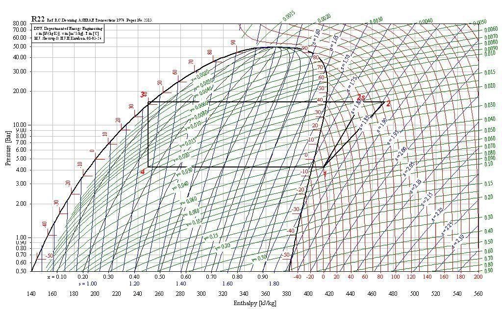
Ok info taken on cool pack this is what i have come up with.
ok looks like i cant post images yet you'll have to wait. ill do my best to explain what ive got EDIT - i can post images now so the p - h diagram is posted down further
Point one begins in the superheated are to in the vapor section of the diagram. i started at -5 deg C and went left to the 10 deg C near vertical line. Now this makes sionce if the super heat was useful, the compressor would have to do less work as apposed if there was no super heat and it started on teh vapor/vapourliquid line. Correct?>
so on the diagram we have the isentropic comp from 1 to 2s following the constant entropy line and the actual compr from 1 to 2. which has to do more work since delta h comp is more. Does this look correct.
Ice man, i am no abit worried about what you mentioning about the suction line does this affect my diagram in anyway or have i done it correct.
cheers allLast edited by ozmecheng; 26-03-2008 at 12:15 AM. Reason: update
-
25-03-2008, 11:32 PM #21
 Moderator
Site Moderator : and general nice guy
Moderator
Site Moderator : and general nice guy

- Join Date
- Sep 2007
- Location
- Split Croatia
- Age
- 57
- Posts
- 6,151
- Blog Entries
- 6
- Rep Power
- 36
Re: Refriferation cycle question
Of course you could. Upload your picture on some of picture servers (Image shack or similar) and then copy-paste link to that image in window who appears when you left click on insert image icon in advanced reply tab. Originally Posted by ozmecheng
-
25-03-2008, 11:46 PM #22
improving poster
- Join Date
- Mar 2008
- Location
- OZ
- Age
- 38
- Posts
- 23
- Rep Power
- 0
Re: Refriferation cycle question
negative, its complainign about 15 post or more to post URLs and alike
-
25-03-2008, 11:47 PM #23
improving poster
- Join Date
- Mar 2008
- Location
- OZ
- Age
- 38
- Posts
- 23
- Rep Power
- 0
Re: Refriferation cycle question
ignore just trying to get mypost count up so i can post images
-
26-03-2008, 12:01 AM #24
improving poster
- Join Date
- Mar 2008
- Location
- OZ
- Age
- 38
- Posts
- 23
- Rep Power
- 0
Re: Refriferation cycle question
ignore just trying to get mypost count up so i can post images
-
26-03-2008, 12:07 AM #25
improving poster
- Join Date
- Mar 2008
- Location
- OZ
- Age
- 38
- Posts
- 23
- Rep Power
- 0
Re: Refriferation cycle question
ignore just trying to get mypost count up so i can post images
-
26-03-2008, 12:09 AM #26
improving poster
- Join Date
- Mar 2008
- Location
- OZ
- Age
- 38
- Posts
- 23
- Rep Power
- 0
Re: Refriferation cycle question
ignore trying to get mypost count up so i can post images
-
26-03-2008, 12:11 AM #27
improving poster
- Join Date
- Mar 2008
- Location
- OZ
- Age
- 38
- Posts
- 23
- Rep Power
- 0
Re: Refriferation cycle question
ignore just trying to get mypost count up to post images
-
26-03-2008, 12:13 AM #28
improving poster
- Join Date
- Mar 2008
- Location
- OZ
- Age
- 38
- Posts
- 23
- Rep Power
- 0
Re: Refriferation cycle question
ignore this one last one
-
26-03-2008, 12:14 AM #29
improving poster
- Join Date
- Mar 2008
- Location
- OZ
- Age
- 38
- Posts
- 23
- Rep Power
- 0
Re: Refriferation cycle question
ok so here it is the p - h diagram let me know what you think
-
26-03-2008, 01:22 AM #30
VIP Poster
- Join Date
- Aug 2005
- Location
- USA
- Posts
- 5,302
- Rep Power
- 25
Re: Refriferation cycle question
Well, it looks like you got your post count up.
")
The chart looks about right based on a quick look.
There is one other assumption you should list... pressure losses have not been accounted for in the cycle.
Otherwise the top and bottom lines would have a slant in them. As shown the process occurs at constant pressure.
No. If you look at your thermo books they should mention what a control volume is. It is simply a boundary you define for your assumptions. If you state no heat gain or loss in the suction line, this implies the suction temperature remains constant. Originally Posted by ozmecheng
In a real world situation the suction line would absorb heat from the ambient air if the ambient air is warmer than the suction line. Conversely, if the ambient air was cooler than the suction, it would reject heat and also temperature.
Are you having fun yet??
Remember, the suction line in the diagram is the small section of horizontal line from the dew point curve to where the gas enters the compressor suction valve.If all else fails, ask for help.
-
26-03-2008, 01:36 AM #31
improving poster
- Join Date
- Mar 2008
- Location
- OZ
- Age
- 38
- Posts
- 23
- Rep Power
- 0
Re: Refriferation cycle question
yer loving it ice man!! well if you think ive done that component right, i have completed that question, found the mass flow rate and the heat rejection rate in the condenser. Yes i think at this stage we are assuming alot in our classes and not taking niggling things into account, like heat in or out of the system through lines and alike. Thanks all. I will probably be back for the second part of the question
Watch this space!!
Cheers
-
26-03-2008, 08:55 AM #32
 Super Moderator
- Join Date
- Oct 2001
- Location
- Nottingham UK
- Posts
- 5,668
- Rep Power
- 51
Re: Refriferation cycle question
Maybe I should delete all these posts for SPAMMING Originally Posted by ozmecheng
-
26-03-2008, 10:38 PM #33
improving poster
- Join Date
- Mar 2008
- Location
- OZ
- Age
- 38
- Posts
- 23
- Rep Power
- 0
Re: Refriferation cycle question
noooooooooooo come on im trying to learn lol

Similar Threads
-
MICROPROCESSOR DIAGNOSTICS/Differnces beteween TK/CTC
By REEFER-TEK in forum TransportReplies: 12Last Post: 27-03-2011, 04:12 AM -
Actual air-conditioning operation and its cycle
By narongwit12 in forum Air ConditioningReplies: 6Last Post: 02-02-2011, 11:09 PM -
TK basic micro-p features and functions
By REEFER-TEK in forum TransportReplies: 0Last Post: 05-12-2007, 06:25 PM -
Operating 60 cycle scroll compressor with 50 cycle 3 phase current
By megavac in forum CommercialReplies: 5Last Post: 09-08-2007, 01:29 AM -
A question on Heat-Pump.
By lana in forum Technical DiscussionsReplies: 18Last Post: 20-02-2007, 12:15 AM
