
Results 1 to 23 of 23
Thread: VFD parallel motors
-
06-03-2008, 06:32 PM #1

 Veteran Poster

- Join Date
- Feb 2008
- Location
- Norway
- Age
- 57
- Posts
- 446
- Rep Power
- 17
VFD parallel motors
A couple times i have set up VFD systems with 2 or 3 condenser fan motors suplied from one VFD. I dont feel i get the setup right in those instances. Is there anyone here with good know-how on how to set up parallell drive VFD?
-
06-03-2008, 07:49 PM #2
 Moderator
Site Moderator : and general nice guy
Moderator
Site Moderator : and general nice guy

- Join Date
- Sep 2007
- Location
- Split Croatia
- Age
- 57
- Posts
- 6,151
- Blog Entries
- 6
- Rep Power
- 36
Re: VFD parallel motors
Are these condenser fans are identical?
-
06-03-2008, 07:54 PM #3
 VIP Poster
- Join Date
- Aug 2005
- Location
- USA
- Posts
- 5,302
- Rep Power
- 25
Re: VFD parallel motors
Are the fans operating simultaneously at any given speed?
I have worked on multiple motors by a common drive before and they seem to work OK.
However, when you say you have concerns are they related to the actual installation of the VFD or the way it controls the condenser capacity?If all else fails, ask for help.
-
06-03-2008, 09:59 PM #4
Veteran Poster
- Join Date
- Feb 2008
- Location
- Norway
- Age
- 57
- Posts
- 446
- Rep Power
- 17
Re: VFD parallel motors
Yes, identical. Originally Posted by nike123

Yes, simultaneously. Originally Posted by US Iceman
The concern is related to the installation, not the way they are controlled.
When configuring the VFD for a single fan, i enter the motor parameters in the VFD, except there isnt stated the true power of the motor, and run a autotune.
However in parallel installation the autotune is forbidden. I have to enter the sum of the amps and the sum of the estimated true power of the motors in the VFD along with the volt, Hz and rpm. The VFD then calculates the resistance and inductance which it otherwise measure in the autotune function of a single motor install. This is the core of the problem. The calculated value in multi motor install is different than the calculated/autotune value in single motor install due to the different amps and power entered.
I dont know if it is this calculated multi motor value, the calculated/autotune value for single motor install or an other value wich is the correct value for the resistance and inductance of the multi motor install.Last edited by SteinarN; 06-03-2008 at 10:55 PM.
-
07-03-2008, 12:03 AM #5
Moderator
Site Moderator : and general nice guy
- Join Date
- Sep 2007
- Location
- Split Croatia
- Age
- 57
- Posts
- 6,151
- Blog Entries
- 6
- Rep Power
- 36
Re: VFD parallel motors
Just guessing, but i think you could try this: first run auto tune on one fan, and then, if that is possible, take data acquired with auto tune function and sum all data, and enter that sum as data for one motor.
Bear in mind that calculation of parallel resistance and impedance are different then serial.
P.S.
I think calculations need to be done in vectors.
That mean, that I need to refresh that part of my memory.
Last edited by nike123; 07-03-2008 at 12:14 AM.
-
07-03-2008, 01:05 AM #6
 VIP Poster
- Join Date
- Oct 2006
- Location
- Bucks, U.K.
- Age
- 71
- Posts
- 604
- Rep Power
- 18
Re: VFD parallel motors
Hello Steinar,
You whetted my curiosity on this problem, so I have been reading up on this.
When you are running a single motor, the autotune is basically to set up the protection parameters in the drive....as you say winding resistance, such that the drive can calculate the thermal protection of the motor.
The manual that I have for the ALTIVAR 71 drives, says that it is necessary to provide EACH motor with its own thermal protection....a lot of fan motors have built in thermistor or thermal sensor so this should be easy.
I would then use this to operate a contactor to disconnect power to the motor when at fault.
I would also link back to the control side of the drive such that if all motors went faulty then drive would not operate with no load.
It also suggests using a 'simple' V/F control (2 point) as opposed to a multipoint V/F which is used to avoid resonance.
The other point it talks about is only to use 'OPEN LOOP VOLTAGE FLUX VECTOR CONTROL'. Current Flux Vector Control does not support multiple motors.
Obviously it is more involved to set up the drive without Autotune, but basically sum of motor powers = drive rating.
I am sure that using a drive in this config on a multi-fan condenser is much more efficient than cycling fans on and off.
ECM
-
07-03-2008, 08:13 AM #7
Veteran Poster
- Join Date
- Feb 2008
- Location
- Norway
- Age
- 57
- Posts
- 446
- Rep Power
- 17
Re: VFD parallel motors
In low load low ambient condition the fans on my multi fan VFD condensers run at maybe 10-20Hz. The power consumtion at 15Hz is only something like 3-6% of the full 50Hz power if my memory serves me right. But the condenser capasity is roughly 40% of full Hz capasity. Originally Posted by Electrocoolman
For 30Hz operation the fan power is roughly 25% but the condenser capasity is still roughly 70%.
Multi fan VFD operation is much more efficient than cycling fans on and off. When cycling fans the fan power and the condenser capasity is roughly proportional.
-
08-03-2008, 03:00 PM #8
Veteran Poster
- Join Date
- Feb 2008
- Location
- Norway
- Age
- 57
- Posts
- 446
- Rep Power
- 17
Re: VFD parallel motors
I've done som heavy thinking.
Autotune one motor. Record the readings. Enter the sum of the amps and power of the motors. Enter the recorded readings for the remaining parameters.
Is this the proper way to do it?
-
08-03-2008, 03:15 PM #9
Moderator
Site Moderator : and general nice guy
- Join Date
- Sep 2007
- Location
- Split Croatia
- Age
- 57
- Posts
- 6,151
- Blog Entries
- 6
- Rep Power
- 36
Re: VFD parallel motors
What are remaining parameters?
When you make calculations in AC electric circuits you need to do that in vectors:
http://www.faqs.org/docs/electric/AC/AC_2.htmlLast edited by nike123; 08-03-2008 at 04:07 PM.
-
08-03-2008, 04:11 PM #10
Veteran Poster
- Join Date
- Feb 2008
- Location
- Norway
- Age
- 57
- Posts
- 446
- Rep Power
- 17
Re: VFD parallel motors
Hz, voltage resistance, inductive resistance and leak inductive resistance. I'm not sure of the proper english words for it, this is directly translated from danish. Originally Posted by nike123
-
08-03-2008, 04:21 PM #11
Moderator
Site Moderator : and general nice guy
- Join Date
- Sep 2007
- Location
- Split Croatia
- Age
- 57
- Posts
- 6,151
- Blog Entries
- 6
- Rep Power
- 36
Re: VFD parallel motors
Is that Danfoss VFD?
What model or series it is?
-
08-03-2008, 04:29 PM #12
Veteran Poster
- Join Date
- Feb 2008
- Location
- Norway
- Age
- 57
- Posts
- 446
- Rep Power
- 17
Re: VFD parallel motors
VLT 2800. In the VLT 5000 series the "leak inductive resistance" isnt listed.
-
08-03-2008, 04:34 PM #13
Veteran Poster
- Join Date
- Feb 2008
- Location
- Norway
- Age
- 57
- Posts
- 446
- Rep Power
- 17
Re: VFD parallel motors
Regarding previous posts, it should be "reactance" not "resistance".
-
08-03-2008, 04:47 PM #14
Moderator
Site Moderator : and general nice guy
- Join Date
- Sep 2007
- Location
- Split Croatia
- Age
- 57
- Posts
- 6,151
- Blog Entries
- 6
- Rep Power
- 36
Re: VFD parallel motors
I will check literature a litle.
-
08-03-2008, 04:55 PM #15
Veteran Poster
- Join Date
- Feb 2008
- Location
- Norway
- Age
- 57
- Posts
- 446
- Rep Power
- 17
Re: VFD parallel motors
For VLT 2800, parameter 108, 109 and 142.
For VLT 5000, parameter 108 and 109.
-
08-03-2008, 05:26 PM #16
Moderator
Site Moderator : and general nice guy
- Join Date
- Sep 2007
- Location
- Split Croatia
- Age
- 57
- Posts
- 6,151
- Blog Entries
- 6
- Rep Power
- 36
Re: VFD parallel motors
Parallel connection of motors
The frequency converter is able to control several motors
connected in parallel. If the motors are to have
different rpm values, use motors with different rated
rpm values. Motor rpm is changed simultaneously,
which means that the ratio between the rated rpm values
is maintained across the range. The total current
consumption of the motors is not to exceed the maximum
rated output current IINV for the frequency converter.
Problems may arise at the start and at low rpm values
if the motor sizes are widely different. This is because
the small motors' relatively high ohmic resistance in
the stator calls for a higher voltage at the start and at
low rpm values.
In systems with motors connected in parallel, the electronic
thermal relay (ETR) of the frequency converter
cannot be used as motor protection for the individual
motor. For this reason further motor protection must
be used, e.g. thermistors in each motor or an individual
thermal relay. (Circuit breakers are not suitable as protection).
NB!
Parameter 107 Automatic motor adaption,
AMT cannot be used when motors are
connected in parallel. Parameter 101 Torque
characteristic must be set to Special
motor characteristics [8] when motors are
connected in parallel.
-
08-03-2008, 06:15 PM #17
Moderator
Site Moderator : and general nice guy
- Join Date
- Sep 2007
- Location
- Split Croatia
- Age
- 57
- Posts
- 6,151
- Blog Entries
- 6
- Rep Power
- 36
Re: VFD parallel motors
108 Resistance (real part of inductance) Originally Posted by SteinarN
3. The value is obtained through manual measurements:
RS can be calculated by measuring
the resistance RPHASE-PHASE between two
phase terminals. Where RPHASE-PHASE is lower
than 1-2 Ohms (typical for motors > 5.5
kW, 400 V), a special Ohm-meter should be
used (Thomson-bridge or similar Kelvin) . RS = 0.5 x
RPHASE-PHASE .
109 Reactance (imaginary part of inductance)
2. The value is obtained through manual measurements
XS is obtained by connecting a motor
to mains and measuring the phase-phase
voltage U M and the idle current φ .
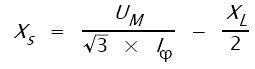
XL: See parameter 142.
142 Leak reactance (sum of rotor and stator
leakage reactance)
This is tricky, I think you should leave it as it is set by factory (or as VFD calculate from "nameplate data").
Also, when you enter parameters 102-106 you maybe don't need to touch these parameters, as it is said in every description for them (like this one for example):
NB!
Parameter 142 The leakage reactance XL
is normally not to be changed if the nameplate
data have been set, parameters
102-106.
-
08-03-2008, 07:10 PM #18
Veteran Poster
- Join Date
- Feb 2008
- Location
- Norway
- Age
- 57
- Posts
- 446
- Rep Power
- 17
Re: VFD parallel motors
Thank you very much nike123 for investigating deply into this subject Originally Posted by nike123

Seems you have the same Danfoss literature as i have. To measure the resistance on small motors is probably not that difficult. However it is not possible to measure the idle current on a fan motor without removing the fan blades. Or maybe i take that job next time.
But to obtain these date isnt realy the problem. We get them in an autotune on a single motor. The question is rather is it ok to enter the single motor data from the autotune, except the power and amps, in a multi motor configuration?
Edit:
Remember the data in 108, 109 and 142 changes as we change the amps and the power. Thus when we enter the sum of the power and amps for several motors, the 108, 109 and 142 also changes. Shall we change them back to the autotune value for a single motor?Last edited by SteinarN; 08-03-2008 at 07:20 PM.
-
08-03-2008, 07:26 PM #19
Moderator
Site Moderator : and general nice guy
- Join Date
- Sep 2007
- Location
- Split Croatia
- Age
- 57
- Posts
- 6,151
- Blog Entries
- 6
- Rep Power
- 36
Re: VFD parallel motors
No it is not OK! VFD see that as one motor, and that mean that you need to find resistance and reactance for combined load. In alternate current systems that is only possible by calculating that with vectors,
So, you need to calculate these values for parallel connection of three inductive load using vectors and real and imaginary numbers. See that link I posted earlier.
-
09-03-2008, 12:00 PM #20
Veteran Poster
- Join Date
- Feb 2008
- Location
- Norway
- Age
- 57
- Posts
- 446
- Rep Power
- 17
Re: VFD parallel motors
Hmmm. I dont think i'm up to that vector calculation.
-
09-03-2008, 06:52 PM #21
Moderator
Site Moderator : and general nice guy
- Join Date
- Sep 2007
- Location
- Split Croatia
- Age
- 57
- Posts
- 6,151
- Blog Entries
- 6
- Rep Power
- 36
Re: VFD parallel motors
I was excellent in high school days. But, that was 23 years ago, and since then, I didn't used that calculations ever again.

And, I think that I am not in the mood to recollect and learn again that skill, which I, maybe, newer again will need.
So, try to find some electrical engineer who will give you support in this mater.
-
09-03-2008, 08:31 PM #22
Veteran Poster
- Join Date
- Feb 2008
- Location
- Norway
- Age
- 57
- Posts
- 446
- Rep Power
- 17
Re: VFD parallel motors
I suppose i have to figure it out by my self. I have a couple VFD's and a couple fan motors in my workshop. I'll do some experimentation and see what results i get.
-
09-03-2008, 10:08 PM #23
VIP Poster
- Join Date
- Oct 2006
- Location
- Bucks, U.K.
- Age
- 71
- Posts
- 604
- Rep Power
- 18
Re: VFD parallel motors
Surely as the 2 or 3 motors are all the same....same manufacture, model, power, fan load etc then the electrical characteristics will be the same....and there is no need to resort to summation of vectors. This would surely only be necessary when trying to sum motors with different power and phase angles?

Similar Threads
-
EC and Air cooled condensers working in parallel
By Josip in forum NH3Replies: 9Last Post: 30-01-2009, 07:50 AM -
Electric Motors - Fans - blades
By MrReds in forum Refrigeration BooksReplies: 5Last Post: 23-11-2006, 07:56 PM -
About parallel compressor system
By ernestlin in forum Technical SpeculationsReplies: 4Last Post: 13-09-2006, 03:34 AM -
Fasco motors
By weeksy in forum ElectricalReplies: 2Last Post: 30-06-2006, 07:52 PM -
Frozen Evaporator Motors
By Brian_UK in forum CommercialReplies: 15Last Post: 03-05-2002, 11:19 PM
